Scope & SG is a very good start. Even better if the SG can make square waves.Hi jhstewart9, I do not pretend to be a knowledgeable tube amp designer, but to learn something new every day.
I'm a Mechanical Engineer and I design processing for the beverage, so a totally different field.
I already have a signal generator and an oscilloscope, but I'm moving to a new house and I don't have a dedicated room for them at the moment. If you don't like the "how it sounds" question, just report what you think it's useful to know about it.
Thanks.
In this end of the World Electrical Engineers are required to have a good knowledge of other engineering fields as well.
For some of us the education & training was very long & involved. Along the way I had experience with jet engine fuel systems
& land survey (Civil Engineering}. I finally got the license when I was 31 yrs old.
But I'd started building electrical things when I was 10 yrs old. It takes a while before good things happen.
I'll get some measurement data on that amplifier for you in the next few days.
I never put that amplifier into an article for publication, another contract in the hitech business came at 73 yrs old.
How cool is that?
Attachments
The main problem , in MY opinion, is there are some people that continuosly post simualations with a lot of variations on circuit and, of course, alteration on virtual test lab.
But nothing was built! Just in some rare case by the forumer with a robust story.
I mean, to build a simple circuit that follow the basic circuit presented then followed by a few standard test.
With a scope and a generator what do you think we can see?
THere are some sw as ARTA with a good sound card and a good interface to attenuate, in case, the input signal, that can help a lot. The BW is limited to 96 kHz but it helps in every case.
I have seen simulationon tube amp included the OT trafo!!
In which way you can simulate a OT?
Someone can help me to understand?
When at low and high frequency each trafo has a proper specification that varies from others. And the variations means not only frequency answer but THD vs Frequency, probably the most important measure .
My idea is that someone think to get a "certificate" of designer with the way of simualtion.
The answer on post 100 it is indicative.
Walter
I did biology and mechatronic, but in another era so it was programming and communication in digital, not analog.
Things changed alot in last decades, and everything goes towards sectoriality (that I do not consider a good thing).
My SG is very basic but can do sine, tri, square. Thank you in advance for the data you will share!
Things changed alot in last decades, and everything goes towards sectoriality (that I do not consider a good thing).
My SG is very basic but can do sine, tri, square. Thank you in advance for the data you will share!
Again, in MY opinion, first step is to fix a good test set not expensive but functional.
Then spend money to build protos that follows the simulations, OTHERWISE it is a lost time!!
But to do this it is expensive!
This is the only way to have a practical results and considerations.
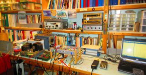
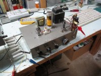
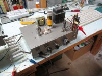
If you look on my lab the dozen of kilos of trafo in different form you can understand what I mean.
In Italian there is a popular phrase " non si può avere la botte piena e la moglie ubriaca"
Translation ( maybe not perfect) : Is not possible to have a barrel full of wine and the drunk wife " (it is not elegant but maybe clear)
I repeat, are MY opinions
Walter
Then spend money to build protos that follows the simulations, OTHERWISE it is a lost time!!
But to do this it is expensive!
This is the only way to have a practical results and considerations.
If you look on my lab the dozen of kilos of trafo in different form you can understand what I mean.
In Italian there is a popular phrase " non si può avere la botte piena e la moglie ubriaca"
Translation ( maybe not perfect) : Is not possible to have a barrel full of wine and the drunk wife " (it is not elegant but maybe clear)
I repeat, are MY opinions
Walter
Finally got back to this amp. Keep in mind it was not built for hifi but looks like it performs well.
My objective was to try PP 6V6s in Class AB2, grids to be driven by CFs
The PS was made small, I wanted to look at the PS on recovery from transients.
And explore NFB back to the upper grids of a differential cascode stage.
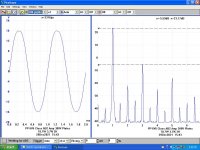
Distortion measurements in this group are made in the usual way plus one set is SMPTE,
Society of Motion Picture & Television Engineers. They use a 2-Tone signal, something at
each end of the audio spectrum. I use 80 Hz & 5 KHz in this case. The measurement looks at how
much the 5 KHz tone is modulated by the 80 Hz. This test is much more difficult for a typical amp to pass.
The SA is a Pico Technology of 10 MHz BW, The Differential Probe used has a BW of 25 MHz.
The spectrum displays in some cases a shewing some artifacts caused by fold back
of the frequency spectrum. More on that later. It is as important for the experimenter
to know what his equiopment cannot do as well as what it can.
At a One Watt level the amp is 3 db down at 13 Hz & 25 KHz. That should satisfy
most listeners except those with Bat's ears.
More on this amp later. And SMPTE.
My objective was to try PP 6V6s in Class AB2, grids to be driven by CFs
The PS was made small, I wanted to look at the PS on recovery from transients.
And explore NFB back to the upper grids of a differential cascode stage.
Distortion measurements in this group are made in the usual way plus one set is SMPTE,
Society of Motion Picture & Television Engineers. They use a 2-Tone signal, something at
each end of the audio spectrum. I use 80 Hz & 5 KHz in this case. The measurement looks at how
much the 5 KHz tone is modulated by the 80 Hz. This test is much more difficult for a typical amp to pass.
The SA is a Pico Technology of 10 MHz BW, The Differential Probe used has a BW of 25 MHz.
The spectrum displays in some cases a shewing some artifacts caused by fold back
of the frequency spectrum. More on that later. It is as important for the experimenter
to know what his equiopment cannot do as well as what it can.
At a One Watt level the amp is 3 db down at 13 Hz & 25 KHz. That should satisfy
most listeners except those with Bat's ears.
More on this amp later. And SMPTE.
Attachments
-
 009 One Watt 345V Int Supply D%.JPG94.8 KB · Views: 113
 -
 007 10W 324V Int Supply D%.JPG91.7 KB · Views: 104
 -
 006 15W 311V Int Supply D%.JPG102.5 KB · Views: 93
 -
 010 18.7W 300V B+ Int Supply D% Clipping.JPG109.8 KB · Views: 103
 -
 011 26W 350V B+ Ext Supply D% Clipping.JPG92.1 KB · Views: 99
 -
 005 6W 344V Int Supply IMD% 80Hz & 5 KHz 4 to 1.JPG96.3 KB · Views: 116
 -
 IMG_6383 to 6384 Work Bench 12W E.jpg621.8 KB · Views: 92
Thank you jhstewart9, that amp is indeed performing well! I will look better at all plots this evening, but what causes that 2nd harmonic peak? A 3rd harmonic cancellation?
I will take inspiration from your work bench for my hobby bench!
I will take inspiration from your work bench for my hobby bench!
SMPTE Official Definition
SMPTE intermodulation distortion test: The amplifier is fed a dual tone signal, 60Hz and 7kHz in a 4:1 ratio. The intermodulation distortion is the percentage of the residual RMS measured at the output (after filtering the test tones out) compared with the total RMS measured at the output.
Or how I do it with the PicoScope SA attached.
I ran a Decware clone on the test bench, the IMD was 9.74% while the output was 260 mWatts. The Decware amp always clipped at less than one Watt.
For a point of comparison I pulled an all 2V tube PP 33s amplifier off the shelf & ran the same test. At 820 mWatts the IMD was 2.67% . The PP 33 Amp clips at ~4.8 Watts.
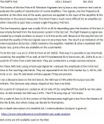
To determine the internal resistance of the amplifier as seen by the load I measured the output voltage with & without the load connected. The internal resistance at One KHz looks like 5.09R, so the Damping Factor (DF) is 7.5/5.09 or ~1.47. About what we would expect from much biased pentodes with only 8 db NFB. But how much of that is the OPT?
Another set of similar measurements at the primary of the OPT shews a much better result. The internal resistance at that point looks like 3.39K, so DF is 6.7/3.39 or ~1.98. The amplifier could benefit from a better OPT.
Running the audio up slowly I found the 3H to be less than the 2H at ~10.5 KHz. But more at other levels. People building distortion cancelling circuits may not be getting what they expect!
SMPTE intermodulation distortion test: The amplifier is fed a dual tone signal, 60Hz and 7kHz in a 4:1 ratio. The intermodulation distortion is the percentage of the residual RMS measured at the output (after filtering the test tones out) compared with the total RMS measured at the output.
Or how I do it with the PicoScope SA attached.
I ran a Decware clone on the test bench, the IMD was 9.74% while the output was 260 mWatts. The Decware amp always clipped at less than one Watt.
For a point of comparison I pulled an all 2V tube PP 33s amplifier off the shelf & ran the same test. At 820 mWatts the IMD was 2.67% . The PP 33 Amp clips at ~4.8 Watts.
To determine the internal resistance of the amplifier as seen by the load I measured the output voltage with & without the load connected. The internal resistance at One KHz looks like 5.09R, so the Damping Factor (DF) is 7.5/5.09 or ~1.47. About what we would expect from much biased pentodes with only 8 db NFB. But how much of that is the OPT?
Another set of similar measurements at the primary of the OPT shews a much better result. The internal resistance at that point looks like 3.39K, so DF is 6.7/3.39 or ~1.98. The amplifier could benefit from a better OPT.
Running the audio up slowly I found the 3H to be less than the 2H at ~10.5 KHz. But more at other levels. People building distortion cancelling circuits may not be getting what they expect!
Attachments
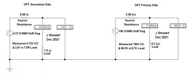
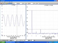
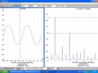
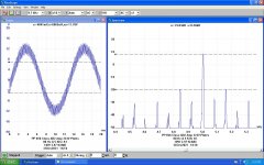
The First Watt is the most important, here is what that looks like on this PP Class AB2 Amp
using the SMPTE Test. Less than One % IMD. That is the degree to what the 5 KHz part of the
test signal is distorted by the 80 Hz LF Tone.
The upper & lower sidebands are identified. They are not at the input, something added by
the amplifier itself. A test most people would never do now but was fairly common in the past.
Many folks with 'fine amps' would not want their jewel tested in this way!
Attachments
jhstewart9,
Thanks for that story and graph. And the earlier postings; a very intensive study of various circuit effects.
Very interesting.
The graph shows that the 160Hz sidebands are stronger than the 80Hz sidebands.
My Denon Audio Technical CD has 250Hz and 8020Hz at 4:1 (info for newbies: 8020 at -12 dBc).
Left only 0dB; Right only 0dB; L and R -10dB full scale DAC output.
It also has 11kHz plus 12kHz 1:1 for 3rd order IMD testing. L 0dB; L 0dB; and L and R -10dB full scale DAC output.
The date on the CD is 1984. Unfortunately it probably is now Un-Obtanium (can't purchase one anymore).
When I got it, it was much cheaper than a SMPTE capable signal generator. But who knows the price of a used one . . . out of sight?
Just took a quick look on eBay, none of those hobby type analyzers on sale today.
But for those still with cash after Christmas some nice more exotic offerings.
For the ordinary experimenter these daze the best way appears to be some kind of
digitally based spectrum analyzer. Ordinary scopes appear to be 8-bit resolution,
so 48 db is theoretically possible. That is barely enough, 12-bit works for me with
an older PicoScope Scope/SA. I've also got an even older 16-bit PicoScope but
don't use it much now.
The 2-channel 200 MHz PicoScope sts on the shelf most of the time. It has a built
in ARB, very useful at times.
There are simple audio generators on the market at a reasonable price. If an
analogue gen suits you there are many simple circuits published. Some need only
a 9V battery as the PS.
I got the HP200CD at an auction. It was AOK when new tubes were stuffed in.
At one time the 200CD was the most numerous sold product in the HP line,
It was a very easy sale. The GAG generator I bought from the guy who had that line here.
I've a 3rd audio generator built myself while I interned (1957) & money was tight. It is a
clone of a Heathkit Audio Generator, a bridged T Oscillator. Complete with the Bill Hewlett
stabilizing bulb, Still works great every time I pull it off the shelf. Not pretty tho!
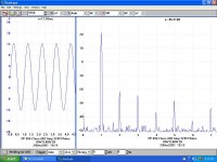
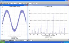
On these SMPTE shots as the power is increased many more sidebands shew up
at 80 Hz intervals.
But for those still with cash after Christmas some nice more exotic offerings.
For the ordinary experimenter these daze the best way appears to be some kind of
digitally based spectrum analyzer. Ordinary scopes appear to be 8-bit resolution,
so 48 db is theoretically possible. That is barely enough, 12-bit works for me with
an older PicoScope Scope/SA. I've also got an even older 16-bit PicoScope but
don't use it much now.
The 2-channel 200 MHz PicoScope sts on the shelf most of the time. It has a built
in ARB, very useful at times.
There are simple audio generators on the market at a reasonable price. If an
analogue gen suits you there are many simple circuits published. Some need only
a 9V battery as the PS.
I got the HP200CD at an auction. It was AOK when new tubes were stuffed in.
At one time the 200CD was the most numerous sold product in the HP line,
It was a very easy sale. The GAG generator I bought from the guy who had that line here.
I've a 3rd audio generator built myself while I interned (1957) & money was tight. It is a
clone of a Heathkit Audio Generator, a bridged T Oscillator. Complete with the Bill Hewlett
stabilizing bulb, Still works great every time I pull it off the shelf. Not pretty tho!
On these SMPTE shots as the power is increased many more sidebands shew up
at 80 Hz intervals.
Attachments
Why you don't try ARTA sw with a good sound card? Or VA sw
And Millet interface/attenuator?
Or REW sw with sound card.
And Millet interface/attenuator?
Or REW sw with sound card.
why you want to pass in overheating in any of the operating point in EL34? you beed to be conservative in designing, forget about maximum of the maximum, nobody is listening hi-fi on maximnum, usually is 1-10W normal listening power.Thank you sarcastic1,
so a steeper loadline would be better than a flatter one?
I will use the datasheet suggested 1k screen resistors with UL taps.
G1 will be dc coupled to the driver stage, through 1k grid stoppers.
They will run in fixed bias, with 1 Ohm on cathodes to check the cathode current.
steeper curve is better because you have less G2 current, and for sure direct coupling AB2 class is not something what you want to use with EL34.. because g1 screen is the weakest point of all tubes, specially which are not designed for dissipating power on them.
for abusing you have per example cheap and nice PL-EL36, there you can do anything, and will not be damage if you push too much.. and also you have 45Watts in AB2 class! for AB2 class also you can use in transmitter tubes which are designed for is , and is stated in the datasheets (6L6GC have data for AB2 class, 2E22 - where is stated also power alowed on grid g1- drive power like 0.55 Watts alowed fro 2E22). RS 1003 or SRS551 is designed for direct coupling and A2 drive mode.. and many others
jhsteart9, 6A3sUMMER, will uploading those CDs infringe any law? It would be great to have them on the forum to perform some tests.
Thank you bepone, I don't want to build a thermoionic heater, but I'm curious about what are considered acceptable limits.
yes, undersood .Thank you bepone, I don't want to build a thermoionic heater, but I'm curious about what are considered acceptable limits.
the colder the tube is, the longer it will last.. temperature is reducing the life significantly..nobody will know if you are extracting 25 or 35W (how much is it in dB? not worth to mention ) of 2 UL connected EL34 but from the aspect of reliability this can go in wrong way. if you are cooling the tube with the external fan, then you can prolong the durability. i'm always reducing the output in favor of the tube life, tubes are expensive, no need to burn them fast for few watts more 🙂
Thanks again bepone,
everything started with a selfbuilt Hi-Fi I've bought on an italian forum, with OPT having 40%UL taps and Raa 3.5 kOhm.
I worked on the phase splitter (it is an hybrid cascoded differential phase splitter with CCS tail) and then connected my 8 Ohm speakers to the 4 Ohm tap.
Here I've been erudited on what I was hearing when I switched to 7k: way less IMD.
On the other side, that amp played for years before coming in my hands, and tubes are still fine. But it can just be a lucky quartet.
In any case, by now I prefer higher loads rather than low ones on all tubes I've built amps with, but there could be other ways to do it better.
Just be aware of the three tube ratings. Rule of thumb: Absolute maximum (used these days) are about 10% higher than design centre.
The 25 watt anode dissipation should under no circumstances be exceeded, best to stick to no more than 22.5Watt to enjoy expected tube life.
http://www.r-type.org/articles/art-257.htm

The 25 watt anode dissipation should under no circumstances be exceeded, best to stick to no more than 22.5Watt to enjoy expected tube life.
http://www.r-type.org/articles/art-257.htm
ARTA looks interesting. But doesn't replace what I'm using now.Why you don't try ARTA sw with a good sound card? Or VA sw
And Millet interface/attenuator?
Or REW sw with sound card.
Looks like the BW is rather limited. And audio output level limited as well.
But might be interesting to try sometime. Maybe later.
Lots to do here aside from DIY. Today I spent a couple of hours
on a tractor pushing snow.
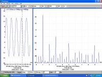
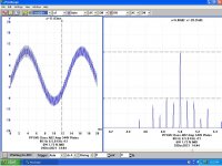
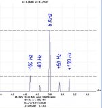
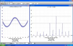
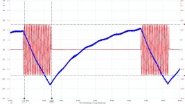
This pulsed One KHz at +15 Watts run on a PicoScope 3224 running driver
r6.8.8 on an olde HP laptop loaded with WIN XP Professional.
The blue trace shews B+ dropping almost 6V delivering that power to
the 7.5R load on the H125E OPT.
I've also got the Pico Driver running on a Dell with WIN 7 Prof.
Attachments
zintolo,
Unfortunately, All Rights of the "Denon Audio Technical CD" are Reserved.
It was produced in Japan.
Lawyers might advise against copying and distributing.
Sorry, I will not copy the CD.
Unfortunately, All Rights of the "Denon Audio Technical CD" are Reserved.
It was produced in Japan.
Lawyers might advise against copying and distributing.
Sorry, I will not copy the CD.
- Home
- Amplifiers
- Tubes / Valves
- Lowest safe loadline: what is the limit?