And I like your use of bridge-T for the bandpass core (asuming you use an inverting OpAmp bandpass), I also find that superior to the simple R/2+2C + R//C bandpass as it has higher Q at the same gain (and it has the same noise gain, so no penalty here), and the higher the gain the higher the Q whereas for the simple bandpass the Q is fixed and low. Equal capacitor values are another bonus.
Any chance to share the circuit with us 😀
Any chance to share the circuit with us 😀
Note the addition of a low-pass output that could be used with a high-impedance buffer, which might be a starting point for an additional lowpass. I have not checked yet if that lowpass is actually better wrt to harmonics or not as the caps do not go to "clean" nodes. OpAmp distortion would still factor in it seems, even with perfect passive parts.
Curves for 0dB gain:
The lowpass output from the Bridged-T is 2nd order which is nice
Curves for +12dB gain:
Here the lowpass would already help H2 by more than 12dB, but see disclaimer above.
Hi,I'm not questioning your experience here but input impedance (DM) difference is negligible (as per datasheets): 30k for 4562 and 20k for 1612.
Fully agree on the loading, though ususal loads like (pre)amp inputs are benign.
And I like your use of bridge-T for the bandpass core (asuming you use an inverting OpAmp bandpass), I also find that superior to the simple R/2+2C + R//C bandpass as it has higher Q at the same gain (and it has the same noise gain, so no penalty here), and the higher the gain the higher the Q whereas for the simple bandpass the Q is fixed and low. Equal capacitor values are another bonus.
For injection-locking a lower Q might be a better choice, though (gut feeling as of yet).
Speaking of which, this evening I was about to try it with the Viktors but for the life of my I can't find the oscillator in my lab, misplaced it somewhere... damn it...
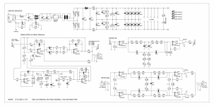
the bridged-T network acts as an Notch Filter and is connected to the inverting input of the oscillator opamp. The voltage divider including the FET is connected to the non-inverting input of the same OPAMP.
Yes, that would be the simplest circuit, with positive feedback adjusted by a FET.Hi,
the bridged-T network acts as an Notch Filter and is connected to the inverting input of the oscillator opamp. The voltage divider including the FET is connected to the non-inverting input of the same OPAMP.
This variation of the Bridged-T cell is the conjugate of the one shown above but actually either version works in both circuits.
I admit that that is also the circuit I'm going to materialize in case I finally will do my own simple Osc.
EDIT: Here also the lowpass-tap seems worthwile as the cap goes to GND (which was the reason I chose the cell gender).
Do you have any experience which notch depth works best? It is obvious that the deeper you go there the less positive voltage feedback is needed to sustain oscillations which helps to keep FET voltage low but there might by side effects which limits this approach (besides getting very large component value ratios). If not, a Hall notch (CRCRC//12R or its conjugate) might even be better than a Bridged-T.
Last edited:
Hi,Yes, that would be the simplest circuit, with positive feedback adjusted by a FET.
View attachment 1014611
This variation of the Bridged-T cell is the conjugate of the one shown above but actually either version works in both circuits.
I admit that that is also the circuit I'm going to materialize in case I finally will do my own simple Osc.
EDIT: Here also the lowpass-tap seems worthwile as the cap goes to GND (which was the reason I chose the cell gender).
Do you have any experience which notch depth works best? It is obvious that the deeper you go there the less positive voltage feedback is needed to sustain oscillations which helps to keep FET voltage low but there might by side effects which limits this approach (besides getting very large component value ratios). If not, a Hall notch (CRCRC//12R or its conjugate) might even be better than a Bridged-T.
the transfer function of the bridged-T network at resonance frequency is 1/( 1+k^2/2) where k^2 is the ratio between the two capacitors. If you swap R and C and vice versa you will have two equal C's and two different R's. The transfer function is equal. With C = 100nF R is 1/(2*Pi*100nF*1000Hz) = 1591.549 R. With k = 7 you get for R_A 7*1591.549R = 11140.846R and R_B 1591.549R/7 = 227.364R. R_B is the resistor with one leg two ground. The voltage divider at the non inverting input of the oscillator opamp must also realize 1/(1+k^2/2). In earlier versions I have set C = 100nF and k = 4.866 . This also works very well.
Regards
Helmut Sell
I'm enjoying this exploration.
Note that in this bridged-T topology, any distortion artifacts arising at the FET pass almost directly to the output without being attenuated by the filter network. This is one advantage of Victor's topology, I believe.
Note that in this bridged-T topology, any distortion artifacts arising at the FET pass almost directly to the output without being attenuated by the filter network. This is one advantage of Victor's topology, I believe.
This is true. But if you make sure that the drain-source voltage at the FET is less than about 30-40mV and the FET is linearized by negative feedback, you can also get below -140 dB THD at 2.5V here with optimal dimensioning. You can get a THD+N < -118dB here using the R and C values I posted. I measured -117.5 dB THD+N at 3V RMS with my R&S UPL. This is then the noise floor of the analyzer.I'm enjoying this exploration.
Note that in this bridged-T topology, any distortion artifacts arising at the FET pass almost directly to the output without being attenuated by the filter network. This is one advantage of Victor's topology, I believe.
No disagreement. I'll also note the bridged-T plus active stage in the KSTR pic is similar to the oscillator in the HP339A. HP design used C12/C10 = 100/1.
Yes. In the HP339A oscillator there works a VCR2N FET. The Drain Source On-Resistance is between 20-60 Ohm. Because of the high ratio k=10 the voltage divider must be designed with low resistance values. In my oscillator design I use the VCR4N FET. The Drain Source On-Resistance moves around 400 Ohm. That is is a better solution when you work with lower k .
I had thought the Siliconix VCRxN were long gone but to my surprise I see Interfet does still make them, though quite expensive...
Helmut, thanks for these details.Hi,
the transfer function of the bridged-T network at resonance frequency is 1/( 1+k^2/2) where k^2 is the ratio between the two capacitors. If you swap R and C and vice versa you will have two equal C's and two different R's. The transfer function is equal. With C = 100nF R is 1/(2*Pi*100nF*1000Hz) = 1591.549 R. With k = 7 you get for R_A 7*1591.549R = 11140.846R and R_B 1591.549R/7 = 227.364R. R_B is the resistor with one leg two ground. The voltage divider at the non inverting input of the oscillator opamp must also realize 1/(1+k^2/2). In earlier versions I have set C = 100nF and k = 4.866 . This also works very well.
Regards
Helmut Sell
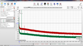
Played around with notch filter types for the non-inv single Op Osc, (degenerated) Hall vs Bridged-T and grounded-R vs grounded-C, for k=10 (yielding -34dB notch), for a 1kHz notch and 100nF of nominal capacitance.
The best compromise is the Bridged-T grounded-R (equal C's and k-spread R's), the type that Helmut is using:
Comparing Bridged-T grounded-R (green) and grounded-C (red)

The best compromise is the Bridged-T grounded-R (equal C's and k-spread R's), the type that Helmut is using:
- reasonable part values, equal caps
- low noise around and above osc freq
Comparing Bridged-T grounded-R (green) and grounded-C (red)
Further to my earlier post about a 1612 buffer:
https://www.diyaudio.com/community/threads/low-distortion-audio-range-oscillator.205304/post-6907123I've now replaced 1612 with OPA1656 on the same PCB, and was pleasantly surprised by the results.
Comparing the respective ouput spectra (see attachment, the spectra are separated for visibility, red is the oscillator), integrated noise at buffer output (400 to 22000Hz) is higher by only 1.6dB, the 2nd harmonic hasn't changed and the 3rd one is higher by 2dB.
On the other hand, given that under similar conditions (3V, load 2K) TI measured the 2nd and 3rd levels below -160dBc (see Fig. 12 in the DS) it shouldn't come as a surprise.
So my oscillator becomes now a 50 ohm output with enough current (two 1656 sections in parallel).
Regards,
Braca
Attachments
See here some example of AP measurement of Vic oscillator:then post a correct test setup verified by a quality measuring device like AP or R&S. Nobody in the professional field trusts PC sound cards and subsequent software calculations. Especially not if you want to correctly measure a THD below -140dB. User KSTR #9493 has measuered Viktors oscillator with an AP SYS 2322. The THD was 10*log(10^(-144db/10) + 10^(-138db/10)) = -137.03dB. Very good value, but well over -140dB.
https://audiosciencereview.com/forum/index.php?threads/e1da-cosmos-adc.27038/post-946458
Martin
Thank you for sharing this. Very impressive. Is it the latest Vic build?See here some example of AP measurement of Vic oscillator:
https://audiosciencereview.com/forum/index.php?threads/e1da-cosmos-adc.27038/post-946458
Martin
Very nice , you have the FET to 0V not in serie with the input . Is it the same /same or ...?A new arrangement with Viktor's oscillator that I've come up with over the past few days. Is it practical?
The OPA1656 as follower in non inverted mode has 2H at app. -150dB at 1kHz 2,7VRMS.A new arrangement with Viktor's oscillator that I've come up with over the past few days. Is it practical?
- Home
- Design & Build
- Equipment & Tools
- Low-distortion Audio-range Oscillator