We could use a constant current temperature oven to change the frequency a few Hz. That would be all I need as my notch is 3Hz off.
🙂
🙂
Okay I do understand better now, I just thought it was cool out.
In my hour or so I went from 996 Hz to 999 Hz.
On a warmer day it went from 1000Hz to 1003Hz in an hour.
I guess we have to keep it in an insulated box, not on bench with
gentle breeze flowing over things.
cheers,
... yep Average = 0.
Uhhh ... I don't think so. If the average = 0 then averaging would get you zero noise. Averaging gets you the average, which means in the limit it becomes a flat line at the average value. But not zero.
OTOH, if you do a very long FFT, the bins are getting smaller, so there is less and less noise in each bin which looks like there is less noise. But that's is not the case, the noise doesn't change, it's just that you look through smaller and smaller windows.
In the limit, an infinitely long FFT record would get you apparent zero noise!
Sorry to split hairs, I think it is an important distinction.
Jan
Last edited:
We could use a constant current temperature oven to change the frequency a few Hz. That would be all I need as my notch is 3Hz off.
🙂
No that would be sub-optimal. You'd want a constant temperature oven, that will keep the freq constant. With constant current you have no control over the impact of ambient temp.
Jan
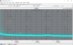
I switched to Praxis because I know how to "bend" it to display usefully. However the base noise level even with an additional 30 dB of low noise amplification (QA470) the harmonics are in the mud. This plot is uncorrected so there is an additional 10 dB of loss at HD2 and 3 at HD3. This still looks like it would not get to where I want to go.
Attachments
... yep Average = 0.
No, with FFT's only vector averaging is to the mean (0), magnitude averaging is to the standard deviation (rms). The resolution floor is the noise floor. When you take the magnitude of FFT's and average them you do not average noise to 0.
Last edited:
But the RTX6001 has an internal xtal clock for the DAC generator, no? That should be more than stable enough for this purpose!
I will try that out this week when I get time.
Jan
Did you find the time to try to work this out or did it go on your to-do list?
I have this naive non-expert idea that one could use one of RTX6001's generator outputs to stabilise the frequency of the Victor oscillator..
Did you find the time to try to work this out or did it go on your to-do list?
I have this naive non-expert idea that one could use one of RTX6001's generator outputs to stabilise the frequency of the Victor oscillator..
Yes that is what I did. Although you cannot set the RTX output frequency to fractional Hz (at least not from within REW), you can set it to any integer Hz frequency and Vic's oscillator will lock to it nicely.
I'm not sure yet if it is enough to center the spectral lines on bins, haven't had time to look in detail.
Jan
Although you cannot set the RTX output frequency to fractional Hz (at least not from within REW),
Just type the decimal value to the generator input field and REW will generate it OK - check in RTA analysis. Only in the generator dialog the input field does not display the decimals.
Just type the decimal value to the generator input field and REW will generate it OK - check in RTA analysis. Only in the generator dialog the input field does not display the decimals.
Ahhh! Thanks, I'll try that!
Jan
I have changed it for the next build to show up to two decimal places if required for the value entered.Just type the decimal value to the generator input field and REW will generate it OK - check in RTA analysis. Only in the generator dialog the input field does not display the decimals.
Great!
I have changed it for the next build to show up to two decimal places if required for the value entered.
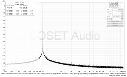
Viktor Sine wave generator V5 balanced and 2X Viktor SE notch filters
Using 2X (to get balanced operaation) of Viktor´s single ended notch filters with -85dB dip according to ARTA (white noise FR2) and Viktor´s sine wave generator V5 in balanced configuration 2,7Vrms SE, I get a bit lower distorsion compared to using my other Twin T balanced notch filter.
H2 = -158 dB
H3 = -163 dB
THD = -155 dB (H2..H21)
According to REW.
It might be that the FKP caps in Viktor´s notch filters give a little lower distorsion than the COG caps I use in my balanced notch.
Attachments
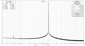
My mistake, I should have injected it at pin 6 of IC2 of course. And then it works beautifully! Vic's oscillator, on itself, runs at around 3003.xx Hz, and drifts a few Hz from turn-on cold. With an injection of 3kHz at 200mV through 560k into pin 6, it snaps to exact 2999.99 Hz, rock-stable from the AP digital oscillator.
There is a fraction of a second re-stabilisation of the level when you turn the injection on or off, but the level returns to exactly the same in each case.
Distortion measurements give the same results as shown above, I don't see any harmonics above -148dBr or so.
The sweet spot seems to be between 150mV and 350mV injection through 560k, going too high starts 3rd harmonic to peek up, going too low shows a very low level 2nd and 3rd (-144dBr) until it looses lock.
Very nice - I now have a locked oscillator and can start to look into synchronous no-window FFT!
Jan
I would like to try this with the RTX and I would appreciate a few more details on how you did it. Was the connection made by a single wire from the +phase of the RTX generator to pin 6 of IC2 (with 560K in series)?
I guess you already have Victor and RTX grounds connected though shield/pin of the balanced interconnect. Or do you make the ground connection differently?
Thanks!
How is the magnitude of the fundamental (48.89 dBFS) related to the "real" one (5.4Vrms, 14.7 dBV)? I.e. what is the full scale (dBFS) in Vrms (dBV)? in your measurement setup?Using 2X (to get balanced operaation) of Viktor´s single ended notch filters with -85dB dip according to ARTA (white noise FR2) and Viktor´s sine wave generator V5 in balanced configuration 2,7Vrms SE, I get a bit lower distorsion compared to using my other Twin T balanced notch filter.
H2 = -158 dB
H3 = -163 dB
THD = -155 dB (H2..H21)
According to REW.
It might be that the FKP caps in Viktor´s notch filters give a little lower distorsion than the COG caps I use in my balanced notch.
5,461 V ACrms .
How is the magnitude of the fundamental (48.89 dBFS) related to the "real" one (5.4Vrms, 14.7 dBV)? I.e. what is the full scale (dBFS) in Vrms (dBV)? in your measurement setup?
I would like to try this with the RTX and I would appreciate a few more details on how you did it. Was the connection made by a single wire from the +phase of the RTX generator to pin 6 of IC2 (with 560K in series)?
I guess you already have Victor and RTX grounds connected though shield/pin of the balanced interconnect. Or do you make the ground connection differently?
Thanks!
The Viktor is powered through a SilentSwitcher from a Powwerbank, so basically floating. I just added an extra BNC connector to the Viktor case, connected the hot to pin 6 through 560k, and connected the BNC ground to the case/Viktor PCB ground.
Then a BNC coax cable to the RTX. But I also tried it with the AP as source, same results.
Jan
Extraordinary hack Jan
Works right away. I used a 680K resistor and BNC connection to the RTX generator output. My Victor is floating so BNC cold was connected to Victor gnd.
RTX output 0 dBV scale (1Vrms). REW generator set to -20 dBV (0.1Vrms), but as I'm using the SE output I guess I actually only apply 50mVrms.
The frequency snaps right to where I set it and remains there. When I turn of the generator it takes a few seconds before it returns to where it was. I did not try more than 0.5 Hz offset.
Distortion does not seem to suffer notably🙂
Attachments
That's about what I saw, but I needed about 100mV for best results. When you want to pull it more than 1Hz or so, you get funny stuff. At one point I saw the output slowly varying on the beat of the freq. difference! I also had one case where the output went to max and the level control didn't do diddly.
So yes, it's a hack, no more. For synchronous FFT I would let the Vic warm up for min. half an hour, so that most of the drift is gone, then check the freq, lock it close to that frequency and then try to get the FFT synchronous with no window. But it's fiddly.
Jan
So yes, it's a hack, no more. For synchronous FFT I would let the Vic warm up for min. half an hour, so that most of the drift is gone, then check the freq, lock it close to that frequency and then try to get the FFT synchronous with no window. But it's fiddly.
Jan
- Home
- Design & Build
- Equipment & Tools
- Low-distortion Audio-range Oscillator