Bob,
I really like your measurement technique and very clear explanation.
If i'm interpreting and computing correctly, the noise floor is 157dB below 3 VRMS, or about 42.4 nV RMS. Do you know what the resolution bandwidth, or even better, the noise-equivalent bandwidth associated with the FFT output? I'm trying to estimate the noise density per root Hertz at the instrument input.
Thanks very much!
Bob,
I really like your measurement technique and very clear explanation.
If i'm interpreting and computing correctly, the noise floor is 157dB below 3 VRMS, or about 42.4 nV RMS. Do you know what the resolution bandwidth, or even better, the noise-equivalent bandwidth associated with the FFT output? I'm trying to estimate the noise density per root Hertz at the instrument input.
Thanks very much!
Thanks for your kind words. Yes, the noise floor is 157 dB below 3 V RMS, or about 42 nV RMS. I'm no expert on FFT equivalent noise bandwidth, but the readout on the QA-401 for the FFT settings used quoted about 0.75 Hz. I would guess this corresponds to the ENBW, but others here would know better. That would seem to correspond to about 48 nV/rt Hz.
As I indicated earlier, it appears from experiments and simulation that the dominant source of noise in the setup is the twin-T filter's thermal noise.
When the compensation equalizer and its amplifiers are run with a shorted input, i.e., the passive twin-T output shorted, the output noise density at 3 kHz is much lower (all in simulation). This is what tells me that the twin-T thermal noise is the dominant noise source in the measurement setup.
However, referring to the complete setup in which the oscillator distortion was measured, this does not take into account any noise contribution from the oscillator.
I thus cannot say whether the twin T noise or the oscillator noise was the dominant contributor in the final measurement. An experiment to further investigate which is the dominant noise source would be to divide all of the twin-T resistances by 10 and multiply all of the twin-T capacitors by 10 and see how much the noise floor went down. If the oscillator was contributing no noise, the measurement noise floor might be expected to go down by 10 dB. However, distortion under these conditions could be expected to go up somewhat due to the increased loading on the oscillator due to the lower impedance of the passive twin-T.
A thorough noise analysis of the oscillator might also shed more light on this question.
Cheers,
Bob
You can get a direct readout of noise density with the QA401. Its buried in a menu somewhere but not too deep. (It was one of my earlier requests.)
Would it make sense to rescale the notch to reduce the noise? Just keep the input Z at 600 Ohms or higher at the notch frequency.
Would it make sense to rescale the notch to reduce the noise? Just keep the input Z at 600 Ohms or higher at the notch frequency.
You can get a direct readout of noise density with the QA401. Its buried in a menu somewhere but not too deep. (It was one of my earlier requests.)
Would it make sense to rescale the notch to reduce the noise? Just keep the input Z at 600 Ohms or higher at the notch frequency.
Hi Demian,
Yes, I've actually used the X-axis /rt Hz readout, and it is convenient, but I have not used it in this context yet. I had previously used it for measurements of 1/f noise in JFETs.
Yes, I could probably scale the twin-T impedances down by a factor of about 10 and maybe get another 10 dB decrease in noise floor of the measurement system. However, in the larger context I am not sure whether the noise floor of the measurement is dominated by noise in Victor's oscillator or in my twin-T. I might be able to get some idea if I do a noise simulation of the oscillator when its agc settings are such that it is just below the point of oscillation. As we know, the Wien bridge in the oscillator is configured as a Wien bridge with a high amount of positive feedback, which essentially makes the Wien bridge a high-Q filter with a great deal of gain, so noise will be multiplied in a frequency-dependent way. The impedances of the tuning elements in the oscillator are similar to those in my twin-T, so I can't rule out the oscillator being the dominant noise source.
Cheers,
Bob
Hi all
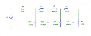
After the pain of going through 900+ pages, I like to suggest a passive low impedance LC brickwall post filter for the 1kHz oscillator to further bring down harmonics and noise.
Connect the filter output directly to dut.
The schematic is the antialising filter of my DAC, scaled down to 1kHz.
Values of air coils and styroflex Cs should still be manageable.
2.2mH or 3.3mH in series for the big ones.
Attachments
Hi all
After the pain of going through 900+ pages, I like to suggest a passive low impedance LC brickwall post filter for the 1kHz oscillator to further bring down harmonics and noise.
Connect the filter output directly to dut.
The schematic is the antialising filter of my DAC, scaled down to 1kHz.
Values of air coils and styroflex Cs should still be manageable.
2.2mH or 3.3mH in series for the big ones.
In theory, this should work fine.
However, I worry about inductor nonlinearity introducing distortion that is bigger than that of the oscillator. The 3 V RMS operating level of the oscillator may be sufficient to drive the inductors into the slightest bit of nonlinearity in the sub-saturation region.
Distortion on the order of -140 to -150 dB is extraordinarily low.
The inductors might also have to be incredibly well-shielded to keep out hum and noise as well.
Cheers,
Bob
Do air inductors distort or go into saturation ?
3 x 2.2mH in series is only 1V per inductor.
I was thinking about LC to eliminate and avoid resistor noise.
3 x 2.2mH in series is only 1V per inductor.
I was thinking about LC to eliminate and avoid resistor noise.
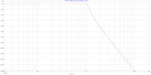
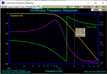
sim
In the real world h2 should be down at least 50dB.
Maybe it does not have to be as steep as that.
In the real world h2 should be down at least 50dB.
Maybe it does not have to be as steep as that.
Attachments
Last edited:
Maybe you attenuate H2 by 50 dB, but the inductors itself introduce new distortion. Solved a problem, created a new one.
FWIW here is the circuit and construction details on the RE CLT-1 Radiometer CLT-1 low pass filter. Its a 10 KHz LP filter that helps get -170 dB at 30 KHz, at least -160 dB passing 1 Watt at 10 KHz. As I remember the internal source is .01% or -80 dB so the filter gets 80 or 90 dB at 2 octaves.
Success is all about construction details. The size of the coils and the size of the shields should help for a sense of scale. For 1 KHz or 100 Hz I don't think you need to scale directly (those would be huge) but I don't know.
There is a matching transformer in it to get to 1 KV or 100 mV into a component. Its a big pot core, almost the size of a bowling ball. Even though the instrument is in a triple case with each module in an aluminium box and the whole system is a double box its still quite sensitive to external fields around 30 KHz which was a problem back in the days of CRT monitors, especially VGA monitors.
Do air inductors distort or go into saturation ?
3 x 2.2mH in series is only 1V per inductor.
I was thinking about LC to eliminate and avoid resistor noise.
Good point. I was thinking in terms of ferrite cored inductors or the like. The air core inductors might not be subject to such distortion, but I'm not sure how big they would need to be, offhand. The point about resistor noise is a good one. That, of course raises the issue of what the input impedance of the filter is, and what the loading is.
So, for example, If I dropped all of my twin-T resistors by a factor of 10 to 1k and increased all of the capacitors by the same factor, I would get about 10 dB less thermal noise from the twin-T network, but now I would have a significantly heavier load on the oscillator.
During my measurements of Victor's oscillator I paralleled various additional resistive loads onto the output, from 1k up to 10k, and did see increases in the distortion of the oscillator (at a 10k additional load it was barely discernable, but at 1k it made the distortion easy to see - somewhere in the -140's).
Cheers,
Bob
Good point. I was thinking in terms of ferrite cored inductors or the like. The air core inductors might not be subject to such distortion, but I'm not sure how big they would need to be, offhand. The point about resistor noise is a good one. That, of course raises the issue of what the input impedance of the filter is, and what the loading is.
3.3mH is not big. Everything would go into a shoe box maybe.
R1 is the output resistance of the oscillator, in this case needs to be exactly 23.8 ohms for the filter to work correctly. Or output impedance of oscillator + R1 = 23.8 ohms.
Load impedance doesn`t matter as long as it is not to low.
Last edited:
Mundorf MCoil BL71 3,3mH :: BL71 :: MCoil AirCore :: Mundorf MCoil :: Inductors :: Passive Components :: Electronic Parts :: Banzai Music GmbH
40x20mm is smallest.
I wonder what it looks like when you add the Rdc of 1.8R.
Patrick
40x20mm is smallest.
I wonder what it looks like when you add the Rdc of 1.8R.
Patrick
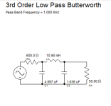
For 1 KHz 28 awg is close to optimum for an inductor. Litz Wire - Litz Design The form factor- diameter to length and the wire lay are both important to getting the max q. The inductors in the CLT-1 are pretty large for 10 KHz so 1 KHz may need to be quite large for optimum performance. Still it may be the best direction. I don't think you need more than 1 inductor and 2 caps to get 18 dB on H2 and 36 db on H3 with one inductor in a 50 Ohm system. I can rescale for 600 Ohms if there is interest. And then inductor design and finally inductor construction and be done with available online tools.
Attachments

I wonder what it looks like when you add the Rdc of 1.8R.
Exactly looks the same... ok, with bigger inductors 0.5 ohm / 3.3mH you have 0.6dB loss at 1kHz.
For 1 KHz 28 awg is close to optimum for an inductor. Litz Wire - Litz Design The form factor- diameter to length and the wire lay are both important to getting the max q. The inductors in the CLT-1 are pretty large for 10 KHz so 1 KHz may need to be quite large for optimum performance. Still it may be the best direction. I don't think you need more than 1 inductor and 2 caps to get 18 dB on H2 and 36 db on H3 with one inductor in a 50 Ohm system. I can rescale for 600 Ohms if there is interest. And then inductor design and finally inductor construction and be done with available online tools.
These are good points.
Post filtering with passive components is not the only way to improve on the distortion of an oscillator like Victor's. As good as Victor's oscillator is, its distortion is still likely dominated by distortion in the JFET AGC element and ripple in the AGC level detector. If this is the case, an active bandpass filter made from equally-good op amps will improve it.
My first step in trying to reduce THD further with his oscillator would be to follow it with a very carefully-designed state variable bandpass filter. Like in Victor's oscillator, it keeps all of the oscillators at virtual ground, making the best of the op amps, but does not suffer any distortion from the nonlinear processes involved in oscillator agc. The SVF BPF post filter might also reduce noise a bit.
Cheers,
Bob
For 1 KHz 28 awg is close to optimum for an inductor. Litz Wire - Litz Design The form factor- diameter to length and the wire lay are both important to getting the max q. The inductors in the CLT-1 are pretty large for 10 KHz so 1 KHz may need to be quite large for optimum performance. Still it may be the best direction. I don't think you need more than 1 inductor and 2 caps to get 18 dB on H2 and 36 db on H3 with one inductor in a 50 Ohm system. I can rescale for 600 Ohms if there is interest. And then inductor design and finally inductor construction and be done with available online tools.
If you scale that to 6oo ohm, the inductor becomes 190 mH
?
Strikes me that this entire thread is a Dueling Banjos interplay--- how best to generate a super-low-distortion source in concert with how to measure what's been achieved. Probably an endless challenge, but fascinating and worthy in it's own right. 😀
I think air-core L-C filters are a useful tool but my own prejudice is toward techniques that might lend themselves to tune-ability across the audio spectrum.
I think air-core L-C filters are a useful tool but my own prejudice is toward techniques that might lend themselves to tune-ability across the audio spectrum.

- Home
- Design & Build
- Equipment & Tools
- Low-distortion Audio-range Oscillator