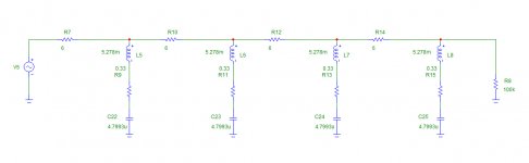
0.33 ohm belongs to inductor
This circuit is only first try.
Small change, for example, 6 ohm to 10 ohm gives notch -120 dB, H2 -6 dB, H3 -3 dB
30, 60, 90, 120, 150dB possible
This circuit is only first try.
Small change, for example, 6 ohm to 10 ohm gives notch -120 dB, H2 -6 dB, H3 -3 dB
30, 60, 90, 120, 150dB possible
Attachments
Last edited:
As good as Victor's oscillator is, its distortion is still likely dominated by distortion in the JFET AGC element and ripple in the AGC level detector. If this is the case, an active bandpass filter made from equally-good op amps will improve it.
My first step in trying to reduce THD further with his oscillator would be to follow it with a very carefully-designed state variable bandpass filter. Like in Victor's oscillator, it keeps all of the oscillators at virtual ground, making the best of the op amps, but does not suffer any distortion from the nonlinear processes involved in oscillator agc. The SVF BPF post filter might also reduce noise a bit.
Bob
I did some weeks ago some simulation with the AGC: servo opamp, fet and opamp. It did not get any stable result using various opamps brands. May the issue comes from the various idle currents of the used opamps as OPA1656 and no real opamp simulation possible (limited model is may the cause).
Only this isolated AGC circuit part draws on simulation up to -120dBFS at Har-2.
IMHO using the FET to a virtual ground is the culprit and did never see this connections on any other schema, also IMHO

While to build an AGC (as used in AP550b) would be the target, but who knows how the build it 😀
Hp
I tried the air-core LC post filter, and ran into two problems:
1. Mains hum. The air core inductor is a super antenna for magnetic fields, just about any mains powered equipment in the same room ruins the measurement.
2. Hysteresis and Mr. Eddy. Don't even think about a steel chassis to kill the hum. Steel sheets half a foot away create more harmonics than you are trying to filter. Even sheet aluminum does this, only at a lower level and due to Eddy currents instead of hysteresis.
With a winding machine for toroids, you could wind the inductor on a wooden donut. A toroidal air core suspended in the middle of some Al shoe box might do the trick.
I tried the air-core LC post filter, and ran into two problems:
1. Mains hum. The air core inductor is a super antenna for magnetic fields, just about any mains powered equipment in the same room ruins the measurement.
2. Hysteresis and Mr. Eddy. Don't even think about a steel chassis to kill the hum. Steel sheets half a foot away create more harmonics than you are trying to filter. Even sheet aluminum does this, only at a lower level and due to Eddy currents instead of hysteresis.
With a winding machine for toroids, you could wind the inductor on a wooden donut. A toroidal air core suspended in the middle of some Al shoe box might do the trick.
Which one did you try ?
Its true, coils need a distance from aluminum. How about copper ? Shielding my DAC clock with copper did wonders.
Also smaller inductors can be used if the capacitances were increased instead.
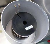
There were pictures of the filter from the super istrument in this thread, if they could do it, we can do it too.
-------------------------------
I have a question fot the original uploader of that picture: Is this magnet wire as used in transformers, speaker coils ? Or does it have a thick insulaion like wire wrap ?
Attachments
Last edited:
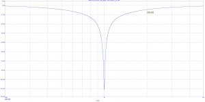
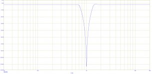
new LC filters... New notch does not affect harmonics.
Before posting any schematic, I will try to make the inductor values as small as possible.
Before posting any schematic, I will try to make the inductor values as small as possible.
Attachments
Last edited:
Which one did you try ?
Its true, coils need a distance from aluminum. How about copper ? Shielding my DAC clock with copper did wonders.
Also smaller inductors can be used if the capacitances were increased instead.
There were pictures of the filter from the super istrument in this thread, if they could do it, we can do it too.
-------------------------------
I have a question fot the original uploader of that picture: Is this magnet wire as used in transformers, speaker coils ? Or does it have a thick insulaion like wire wrap ?
I'll pull it out again. I think its just solid conductor but I'll check. Keep in mind that's for 10 KHz so 1 KHz will be bigger in some ways.
I'll pull it out again. I think its just solid conductor but I'll check. Keep in mind that's for 10 KHz so 1 KHz will be bigger in some ways.
Thanks, if it is to much trouble, not so important.
I was just curious if they used standard enameled wire, maybe silverplated wire, or something special.
I have the feeling that a notch filter made of inductors causes more problems than it solves. Why don't you stick to capacitors and resistors?
True, in particular in case of band-stop (or notch) filters.I have the feeling that a notch filter made of inductors causes more problems than it solves.
Now we are talking about passive band-pass (or low-pass) filters (in order to further bring down harmonics and noise). Not that easy without inductors.Why don't you stick to capacitors and resistors?
Last edited:
True, in particular in case of band-stop (or notch) filters.
Now we are talking about passive band-pass (or low-pass) filters (in order to further bring down harmonics and noise). Not that easy without inductors.
I assume that DIYralf was referring to active filters when he referred to sticking with R's and C's.
I agree with that, both for the case where the oscillator's performance is sought to be improved by a post bandpass or low-pass filter and where measurement if distortion is sought to be improved by a post notch filtering arrangement (which may include a passive twin-T).
If you can make an extremely good oscillator with an extremely good op amp, you should be able to improve the performance of that oscillator with a post bandpass filter using the same extremely good op amp with the same level of careful design, since the bandpass filter has no distortion contributions from agc control circuits (which are the dominating contributor to oscillator distortion when using an extremely good op amp).
Cheers,
Bob
If a LC filter for example had 2 equal inductors in series, could the picked up hum be eliminated by having the signal going through the inductors 1 time clockwise and 1 time counterclockwise, inductors mounted side by side ?
That would assume that the hum picked up in each filter would be exactly the same in magnitude and phase. That will generally not be the case.
Jan
Jan
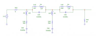
Quick variation with 2 shunt and 2 series inductors
L22, L24 clockwise, L23, L25 counterclockwise.
Same principle as balanced signal transmission.
Inductors of pairs mounted with 1cm space between them.
L22, L24 clockwise, L23, L25 counterclockwise.
Same principle as balanced signal transmission.
Inductors of pairs mounted with 1cm space between them.
Attachments
Last edited:
What is the required or ideal depth of the notch ?
If you want to add 40 dB to the dynamic range of the measurement setup, the depth of the notch should probably be at least 50 dB, better 60 dB.
In my setup, using a specially-designed notch, followed by a THD analyzer, followed by a spectrum analyzer, I designed the twin T to have a controlled, calibrated notch depth of 40 dB, even though the raw twin-T notch achieves at least 60 dB notch depth. A calibrated notch depth limitation in a twin-T is easily implemented by putting a parallel R-C in series with the twin-T's connection to ground. The time constant of that R-C should be the same as the time constant of the R and C of the twin-T arms so as not to alter the frequency of maximum depth.
The deliberately-limited notch depth allows a little bot of fundamental to get through, so as to enable the auto-tune circuits of the THD analyzer to lock onto the test signal.
Dynamic range of this arrangement was pretty much entirely limited by thermal noise from the passive twin-T up front and the noise of the oscillator under test. The noise floor in my setup was in the -150's. Twin T arm resistors were 10k. The FFT length and averaging was significant, but not unreasonable, using a QA-401. Lower impedance in the twin-T would lower the noise floor further if the DUT noise is not dominant. A longer FFT with more averaging could also be expected to lower the noise floor. These issues were discussed in an earlier post.
Cheers,
Bob
thanks, so either -40dB or as much as possible
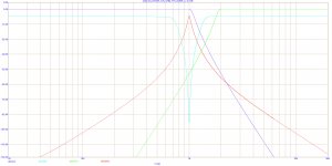
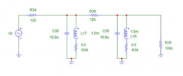
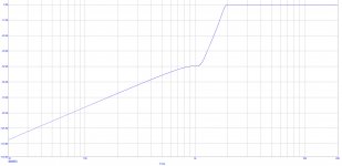
If anybody like to try, here is band pass for post osc filtering with 2 inductors, 1 should carry the signal in opposite direction, h2 -40dB, h3 -50 dB.
R34 is the total source impedance, so if the oscillator output is 50 ohms, R75 needs to be 75 ohms.
To scale for existing values of parts, divide all inductor values by n and multiply capacitor values by n.
Or vice versa.
I can not do tests now, need order inductors first, and all I have at the moment is 16bit fft.
Also I think the final filter should be terminated on both sides with low impedance to shunt the antennas
Attachments
Last edited:
- Home
- Design & Build
- Equipment & Tools
- Low-distortion Audio-range Oscillator