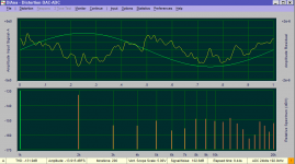
You can change the output series resistor in your board to a different value, but must be metal film. As example, the old boards (LM4562/LME49720) can work with 200 ohm instead of 600.Here is the kind of headache that makes ultra low distortion measurements so difficult. This is two measurements, Victor into RTX. The only difference is the cable. One is much longer 10' conventional shielded coax. The other a shielded two conductor cable maybe 3' long. The longer cable consistantly shows lower HD3 and HD4. I don't think its a capacitive roll off that gets an additional 10 dB. However there could well be some phase shift that cooperates with the internal distortion of the RTX ADC.
Vic.
I tried the external sync and found it can work but it seems to boost the distortion significantly at a level with lock. At least so far. The series resistor is 1M It locks pretty well at 30 mV if you are in the center of the lock range. the lock degrades as you move off the center frequency. This is locked and no notch.
Attachments
I don't think the compensation is working right. I'm getting something of a reverse nonsense on this loopback with the notch.
The harmonics of the output at -18 db should be in the -135 dB range or higher typically. This is reporting -114 H2 which is considerably higher than it should be. Something is not scaling. I used the soundcard selftest and converted that to a correction file but it still did not work it seems the notch is too narrow for tREW to catch it. it shows the phase transition but 20 dB insertion at 994 Hz. I measured 70 dB insertion loss using more conventional instrumentation. I retried the cal routine and got the same -20 dB on the cal sweep even though the reference comes in at -50.
993.1678 -10.7211 -74.61
993.5341 -13.0389 -70.96
993.9003 -15.8539 -63.72
994.2665 -20.0078 -49.08
994.6327 -23.5604 -6.68
994.9989 -21.5273 42.78
995.3651 -17.2324 65.74
995.7313 -13.9259 74.12
996.0975 -11.5546 78.88
Attachments
Here is the kind of headache that makes ultra low distortion measurements so difficult. This is two measurements, Victor into RTX. The only difference is the cable. One is much longer 10' conventional shielded coax. The other a shielded two conductor cable maybe 3' long. The longer cable consistantly shows lower HD3 and HD4. I don't think its a capacitive roll off that gets an additional 10 dB. However there could well be some phase shift that cooperates with the internal distortion of the RTX ADC.
My experience is that with same type of cable, shorter gives better results. Cable types give often large differences in the mains spurs department.
So I have a few coax cables that are short and clean. Classic case of evolution by manual selection ;-)
Jan
I don't think the compensation is working right. I'm getting something of a reverse nonsense on this loopback with the notch.
Demian, John posted some tips. After you get the filter response, you need to uncheck the 'limit max boost to 20dB' check box on the Cal tab in the Measurements screen. Also you need to normalise the filter curve you want to use as cal file to zero dB, but I forgot where that was.
Then do again a loopback response using the cal file and if all is well the result should be a flat line.
Jan
Good work, Jan!
I also use a calibration file in REW as you saw in my post of my THD measurement on my Viktor generator.
Did you do a balanced measurement or single ended?
Have you noticed any difference in THD for singel ended and balanced on the Viktor?
I also use a calibration file in REW as you saw in my post of my THD measurement on my Viktor generator.
Did you do a balanced measurement or single ended?
Have you noticed any difference in THD for singel ended and balanced on the Viktor?
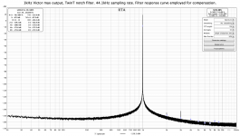
Spend some time over at the REW thread. Managed (with the help of John M) to use the response curve of the twin tee as the eq file for the measurements. Two advantages: automatically take into account the attenuation of the harmonics by the twin tee, and restore the fundamental to its original level.
Great software, check it out! This is the Viktor, 3kHz at 2V out. The numbers are in the left hand corner.
But it takes a lot of averages to get the noise low enough ...
Jan
After messing around in REW I succeeded in generating the filter compensation file and employing it in the measurements. Looks good to me and the data are very consistent with what I measure/calculate without compensation.
What I have to wrap my head around is the various different numbers in that screen (and I have them too, it's not your problem).
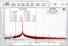
Left top says: 29.4 dBFS, 2nd -159.3
right top: 9.39dBV
the fundamental in the graph is ~9.4dBV
the 2nd in the graph is ~-145dBV
So when I add the fundamental level to the 2nd I get ~-154.4 . How does that jive with the -159.3 in the top left? And what does that 29.4dBFS top left mean?
Jan
Phase compensatinon
That's also how I calculated the coherent FHT (rotating the harmonic vectors).
Cheers,
E.
Hi Pavel,[...]If the chunk does not contain exact periods of fundamental, of course the next chunk will have the fundamental phase rotated. But the harmonics phase should be calculated against zero phase of the fundamental, it is easy to rotate the FFT'd phases to time when fundamental was at zero phase and I think REW does it. I am almost sure it does, otherwise the harmonics phase values would wildly fluctuate every FFT run. [..].
That's also how I calculated the coherent FHT (rotating the harmonic vectors).
Cheers,
E.
I'm also getting rather confusing results at different gain setting of the ADC. I think it has something to do not only with "analog" noise, but also with quantization noise from the ADC. I have to investigate this further,I would like to believe this is an accurate measurement of Victor's oscillator. Nevertheless there are several steps here I'm not so confident of. The process of characterizing the notch and also corrections for different gain settings on the RTX I'm very unsure of at this stage. E.G. if I increase the gain on the test channel to make up for the insertion loss DiAna gets very confused so maybe its too soon to go that far.
So some tracking mechanism would be an unnecessary luxury (I'm working on that too).Also in the hour or so I was doing this my victor drifted from 994 Hz to 995 Hz and DiAna correctly rejected the existing notch filter setting.
Cheers,
E.
I think every software showing harmonics phase against the fundamental or doing vector averaging must do it. For one sine it is trivial. It took me a while to find a method to determine the zero-phase time for any number of tones, but my method works only for integer-Hz tones which all started at one time with zero (or known) phase - i.e. a digitally generated signal wich actually does have a zero time. I use the method for compensating distortions of multitone signals - once the zero time of the combined fundamentals is known, compensating (i.e. time-shifting) FFT'd IMD distortions is simple.That's also how I calculated the coherent FHT (rotating the harmonic vectors).
Correction
I mean, of course, would not be an unnecessary luxury.So some tracking mechanism would be an unnecessary luxury (I'm working on that too).
It took me a long time understand all those numbers, but I think I worked it out.What I have to wrap my head around is the various different numbers in that screen (and I have them too, it's not your problem).
Left top says: 29.4 dBFS, 2nd -159.3
right top: 9.39dBV
the fundamental in the graph is ~9.4dBV
the 2nd in the graph is ~-145dBV
So when I add the fundamental level to the 2nd I get ~-154.4 . How does that jive with the -159.3 in the top left? And what does that 29.4dBFS top left mean?
Jan
All the values recorded and used by REW for distortion calculations are inside the distortion box (upper left). The unit used here is dBFS as this is the unit of the data coming from the RTX.
In the graph main window you can choose what Y-axis unit to use, but you will need to tell REW the scaling factor for it to display correctly. The scaling factor for dBV is the number you insert in the "FS sine Vrms" box. In my case I have here inserted 0.1V as I had the RTX input scale set to -20dBV. This is also why you see 29.4 dBFS in the distortion box (upper left) and 9.39 dBV in the graph window (upper right). The difference is the scaling you entered in the "FS sine Vrms" field. You can enter whatever you want in this field and the distortion calculations remain the same. Only the graph and the upper right number (magnitude of fundamental in dBV) changes.
In the measurement I showed REW tells me that the magnitude of the fundamental is 9.39 dBV, but this is not really true. It is 14.5dBV (full output from victor).
I can correct this manually (which would make the distortion data some 5 dB better🙂), but at least for me this is not a good solution as the hole point of the filter calibration response correction is to get reliable data without having to do post hoc calculations.
I have one idea how one might make it work. If I deliberately offset the oscillator frequency from the notch centre by a couple of Hz I should still have sufficient attenuation of the fundamental (some 55-60 dB). At this frequency, however, the notch curve is much less steep and I would expect the filter compensation to be more accurate and reliable.
Last edited:
Thanks Nic that's helpful, I will look at it again in this light.
The way I used to do it on the AP was setting the Y-scale to dBr, and setting the dBr ref to the level of the fundamental (which I know of course) corrected for the harmonic attenuation, which is 8dB for the 2nd.
So with a 2V (+2dBV) fundamental I would set the dBr ref to 8 dB lower, to -2dBV.
I was hoping that now in REW we can correct exactly for the notch curve, this would be easier. It might be, but I'm not looking through it yet.
BTW I am pretty sure that REW does a perfect job in correcting for the notch. You can easily check that by doing a loopback with the notch between output and input, using the same notch cal file. With the correction you should get a perfect flat response - I did!
Jan
Moving cables away from the sound card and or computer might affect these ultra low measurements, too, I have noted.
There is a guide on how to use REW to measure soundcards. Not sure where...but here.
There is a guide on how to use REW to measure soundcards. Not sure where...but here.
I'll open the box and add the sync next. (or sync X 3 for the three oscillators) The cable thing was pretty consistent across multiple cables and setups. I still like the last measurement number, I just hope its reasonably correct.
I tried REW but I need a guide on how to set it up to match since there are a lot of places to look. I could not see where to add a correction file or how to switch it on and off.
Looks really good and accurate to what I have seen in my "lab" and here.
Is that balanced or single ended measurement?
Is that balanced or single ended measurement?
I would like to believe this is an accurate measurement of Victor's oscillator. Nevertheless there are several steps here I'm not so confident of. The process of characterizing the notch and also corrections for different gain settings on the RTX I'm very unsure of at this stage. E.G. if I increase the gain on the test channel to make up for the insertion loss DiAna gets very confused so maybe its too soon to go that far.
Also in the hour or so I was doing this my victor drifted from 994 Hz to 995 Hz and DiAna correctly rejected the existing notch filter setting.
you can see the full range of the 725D appears to be to -180 floor 😱 [-100 = 0] OMG Can that be true?!
You need to refer the noise floor to nV/rt Hz accounting for noise BW of the window and the FFT gain. We have been through this before where a signal from a 1k Ohm source resistance showed 1nV of noise floor which is not possible.
The input noise of the 725 (all versions) is in the 4 nV/rtHz range. The real limit are the input protection resistors, 1.5K (7W). Its processing is good and with the tweaks and internal upgrades the noise is really limited by thouse resistors and the Jfets, which are followers to a diff pair of bipolars. Not the lowest noise solution.
The high resolution of the FFT does help but only to the point where you run into other noise limits. I'll attempt to duplicate the plot above in the next few days. Need to move stuff around to make room. All these guys are big.
The high resolution of the FFT does help but only to the point where you run into other noise limits. I'll attempt to duplicate the plot above in the next few days. Need to move stuff around to make room. All these guys are big.
Also in the hour or so I was doing this my victor drifted from 994 Hz to 995 Hz and DiAna correctly rejected the existing notch filter setting.
Okay I do understand better now, I just thought it was cool out.
In my hour or so I went from 996 Hz to 999 Hz.
On a warmer day it went from 1000Hz to 1003Hz in an hour.
I guess we have to keep it in an insulated box, not on bench with
gentle breeze flowing over things.
cheers,
with FFT and averaging, any apparent noise is reduced....
Averaging can - and does - reduce the noise pk-pk value but not the average level.
Jan
- Home
- Design & Build
- Equipment & Tools
- Low-distortion Audio-range Oscillator