Since I took a multiple of my x3 chunk to create the longer wav for averaged 4M FFT, the result is still aligned with your chunk and the periods 🙂
Just like the prime factor FFT, it turns out all sample rates break down to no factor over 7 so there is virtually no computational load even using 44100.
I'm just a hobbyist so production testing isn't an issue. Being retired I have no plans to start a new business and audio was never my main line of income, despite doing some serious development work on HDCD and electrostatics.
Are they just limited in functionality? I have never used any sort of AP unit and to tell you the truth having to read the manual for every model seems a bit daunting just for a basic comparison of features.
Whatever I buy it will have to come from overseas. There are none in Australia for sale.
For your purposes a Quantasylum QA401 would be the best fit and value. QA401 Audio Analyzer
– QuantAsylum There is discussion of this and a number of other analyzers around here. You do need a computer to run it but its quite simple, certainly compared to an AP. This should continue in one of the more relevant threads.
You mean the magnitude.
Of course, my wrong.
Not sure why the phase of the harmonics would matter in this case, I've seen nothing discussed here about the phase of the harmonics only the magnitudes.
Well, that is what I do not understand about your point:
looked at in power of 2 chunks the phase rotates slowly on the 3002.9Hz fundamental (and harmonics)
I mentioned that I wanted to try vector averaging which requires perfect phase sync to the input. You need a tool that gives the user access to both the real and imaginary part of the FFT separately.
I am not sure I understand. FFT length is not perfect multiple of the signal period, therefore every FFT the fundamental will yield a different phase. IMO that does not satisfy the condition for vector averaging, the results must be time-shifted to time when fundamental was at same phase as in all the other FFTs - basically to zero phase. That is what I do in the distortion compensation when averaging calibration results (i.e. complex amplitudes of harmonics) from a sequence of subsequent FFTs. And I think that is what REW does too in its distortions display. Or you must trigger the FFT at the same moment of the fundamental period which is not the case of a continuously running series of FFTs.
But maybe you mean something else, I really do not know.
Well, that is what I do not understand about your point:
I am not sure I understand. FFT length is not perfect multiple of the signal period, therefore every FFT the fundamental will yield a different phase.
But maybe you mean something else, I really do not know.
OK that's the mis-understanding, that's what I thought Jan was trying to do, for instance, a 4M file has 64 65k records with exactly the same number of cycles of the stimulus each starting at exactly the same point. What I see is a 180 degree phase shift every 1M points or about 10usec per sec. I could be silly and quote the spec for an Aglient primary reference ( 10**-15/week)
but there are ordinary frequency standards 1000x or more better than 10ppm/sec.
I've done this with for instance with DAC/A/D combo that run off the same clock. Starting anywhere looking at the file as a circular buffer every one of the 64 65k records lines up exactly. The actual sampling rate does not matter if the frequencies are computed properly.
The confusion here over 48k vs 64k has only muddied the water. The frequency lock experiment should be repeated at say 48K where all frequencies are at integer Hz and 48k FFT's should be used for the analysis to see if a perfect lock can actually be achieved.
Last edited:
In the RTX, as far as I can see, you can't have the same FFT length and the same number of samples. In the AP you can (32k FFT length and 32k samples). You also cannot have the same FFT length as the (48k) sample rate.
Jan
Jan
You also cannot have the same FFT length as the (48k) sample rate.
Jan
As far as I can tell the file you sent me had a 65K sample rate so if you could try and lock on an exact integer Hz there would be no ambiguity. As it is if you zoom in on the full 2M bins of the 4M FFT the harmonics do not fall exactly in the bins but when plotted on your screen you don't see that. I don't know if any of this is worth more pursuit.
Scott, I think I see what you mean.
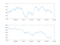
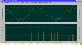
This is output from a simple octave script calculating 655360-long FFTs on blocks starting every 5000 samples, getting fundamental amplitude and phase time-aligned to the first FFT. Analyzed first 3.5mil samples from the original file sent by Jan, avoiding the 12kHz-noisy end of the file.
The first chart is amplitude per FFT offset in the file.
The second chart is phase per FFT offset in the file.
The amplitude deviates, the phase deviates. I can imagine this being caused by the two analog notch filters in the measurement path - a slight change in notch frequency in any of the filters will change the amplitude and phase shift.
Attachments
Last edited:
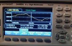
Viktor Sine Wave Generator Freq vs Time Drift
I was curious about how much Viktor´s generator would drift over time. Here is an image showing the frequency drift for one hour. Max output voltage (2,7VACrms). PCB protected from moving air but not in metal casing.
I was curious about how much Viktor´s generator would drift over time. Here is an image showing the frequency drift for one hour. Max output voltage (2,7VACrms). PCB protected from moving air but not in metal casing.
Attachments

Scott, I think I see what you mean.
The amplitude deviates, the phase deviates. I can imagine this being caused by the two analog notch filters in the measurement path - a slight change in notch frequency in any of the filters will change the amplitude and phase shift.
That makes sense, they are not in the loop. I get all the same results that everyone else got with averaging the magnitude only. I was just wondering that if the vector averaging worked the noise floor can be averaged to its mean (0) rather than the rms, sort of like a lock-in amplifier. Wishful thinking.
I think that's what the manual of my Agilent 89441A vector signal analyzer says, too.
I'll look into this next month when I'm ready to test cross correlation.
Quick tests were inconclusive, but there are a thousand things to set up wrong with this thing.
Cheers, Gerhard
I'll look into this next month when I'm ready to test cross correlation.
Quick tests were inconclusive, but there are a thousand things to set up wrong with this thing.
Cheers, Gerhard
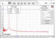
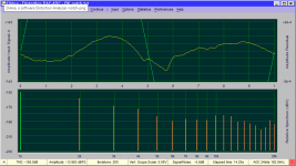
Spend some time over at the REW thread. Managed (with the help of John M) to use the response curve of the twin tee as the eq file for the measurements. Two advantages: automatically take into account the attenuation of the harmonics by the twin tee, and restore the fundamental to its original level.
Great software, check it out! This is the Viktor, 3kHz at 2V out. The numbers are in the left hand corner.
But it takes a lot of averages to get the noise low enough ...
Jan
Great software, check it out! This is the Viktor, 3kHz at 2V out. The numbers are in the left hand corner.
But it takes a lot of averages to get the noise low enough ...
Jan
Attachments
Cant't wait to try this🙂
Jan, I don't understand why you have entered 2.000 in the "FS sine Vrms" box in REW.
I believe that you should here enter the input range that you are using on the RTX.
The distortion calculations will be the same, but I believe the dBV Y-axis scale will be incorrect if you don't do so.
Jan, I don't understand why you have entered 2.000 in the "FS sine Vrms" box in REW.
I believe that you should here enter the input range that you are using on the RTX.
The distortion calculations will be the same, but I believe the dBV Y-axis scale will be incorrect if you don't do so.
My reasoning is that that is the reference for the dBV scale. The source is 2V.
Am I wrong here?
Jan
Am I wrong here?
Jan
I believe it that that it is indeed the reference for the dBV scale. REW needs to know what input amplification/attenuation you use on the RTX to convert the dBFS data it receives to dBV.
Anyway, something is wrong as 2V is not 11.27 dBV.
Anyway, something is wrong as 2V is not 11.27 dBV.
Here is the kind of headache that makes ultra low distortion measurements so difficult. This is two measurements, Victor into RTX. The only difference is the cable. One is much longer 10' conventional shielded coax. The other a shielded two conductor cable maybe 3' long. The longer cable consistantly shows lower HD3 and HD4. I don't think its a capacitive roll off that gets an additional 10 dB. However there could well be some phase shift that cooperates with the internal distortion of the RTX ADC.
Attachments
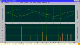
I would like to believe this is an accurate measurement of Victor's oscillator. Nevertheless there are several steps here I'm not so confident of. The process of characterizing the notch and also corrections for different gain settings on the RTX I'm very unsure of at this stage. E.G. if I increase the gain on the test channel to make up for the insertion loss DiAna gets very confused so maybe its too soon to go that far.
Also in the hour or so I was doing this my victor drifted from 994 Hz to 995 Hz and DiAna correctly rejected the existing notch filter setting.
Also in the hour or so I was doing this my victor drifted from 994 Hz to 995 Hz and DiAna correctly rejected the existing notch filter setting.
Attachments
I would check the connector, if the connection is not soldered. After connecting/disconnecting 10 times maybe the measurement will be slightly or more than slightly different. I do a similar ritual every day with cables between the adapter and sound card before working on the distortion compensation - after that the spectrum stays stable. A soldered joint would provide much longer-term reliability in keeping THD < 130dB (i.e. all harmonics below -140dB to fundamental).
Demian you should try the sync injection in Viktor's oscillator. It is a bit finicky to set up but really works.
Jan
Jan
I'll open the box and add the sync next. (or sync X 3 for the three oscillators) The cable thing was pretty consistent across multiple cables and setups. I still like the last measurement number, I just hope its reasonably correct.
I tried REW but I need a guide on how to set it up to match since there are a lot of places to look. I could not see where to add a correction file or how to switch it on and off.
I tried REW but I need a guide on how to set it up to match since there are a lot of places to look. I could not see where to add a correction file or how to switch it on and off.
- Home
- Design & Build
- Equipment & Tools
- Low-distortion Audio-range Oscillator