I finally got my two examples running. Stock they are disappointing given what they started with. The output is sensitive to the negative supply voltage and is too high, especially for 5532's. I get less than .01% but just with strong HD2 and HD3.
Does VR mostly affect 2H ?
-RNM
I finally got my two examples running. Stock they are disappointing given what they started with. The output is sensitive to the negative supply voltage and is too high, especially for 5532's. I get less than .01% but just with strong HD2 and HD3. The AGC level detector seems to be less than ideal and has significant harmonic energy at its output. My first trick was to try to lower the output by changing R12. I think the PCB may be mismarked because its responses more like R13. Lowering to 3V out did not reduce the harmonics significantly. The distortion trim has almost no identifiable effect.
I created a simulation (attached) to see what it happening. It seems the AGC output has enough harmonic ripple that its getting into the JFET and causing the distortion. I'm still not sure what the real contribution of R3 and R10 is supposed to be. I made the simulation so i can try options easier, however even on a fast computer it takes a long time to run. With the stock values for C3 and C4 the output doesn't stabilise in 10 seconds which takes about 10 minutes to run. I reduced both 10X in the simulation pictures and increased R12 to 5 Meg to get the output down. It may be faster to just tweak the board itself.
The diodes listed are fast diodes but not really different from 1N914 and the transistor listed actually has a lower IDss with more C than the one I'm using in the simulation.
I'll play with it some more today.
How much AC voltage is across the FET (d-s)? Seems, that not so small.
It's probably the ripple modulation off the controller driving the harmonic content up.
This can be reduced by narrowing the control range of the Jfet. Get the sensitivity down.
Controlling parallel a 1k resistor seems like way to much. See if you can get it to work with R4 at 100 or 200 ohms.
You might need to adjust R5 as well.
You can also try putting a large cap from gate to ground temperately to see if ripple reduction will bring the harmonics down.
Last edited:
I looked more with the simulation. The waveform at the output of the TL071 is identical to the harmonic residue. Increasing the integrator caps would reduce it and lengthen the settling time. I agree the FET has too much control and both lowering R4 and possibly a resistor in series with the FET will help but I want to clean up the integrator first. I figured out that R10 is actually to reduce the ripple and it does work some but there will still be some no matter what. I'm thinking maybe a diode on the output with a cap would have a more significant effect, but still needs a discharge path. All valid experiments.
I looked more with the simulation. The waveform at the output of the TL071 is identical to the harmonic residue. Increasing the integrator caps would reduce it and lengthen the settling time. I agree the FET has too much control and both lowering R4 and possibly a resistor in series with the FET will help but I want to clean up the integrator first. I figured out that R10 is actually to reduce the ripple and it does work some but there will still be some no matter what. I'm thinking maybe a diode on the output with a cap would have a more significant effect, but still needs a discharge path. All valid experiments.
Yes R10 is connected to an inverted copy of the LP output but this the HP output and will increase the noise. Not sure a 1Mohm resistor there will do much anyway.
It's back to stuff we discussed 3 - 4 years ago.
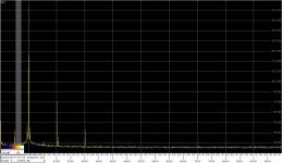
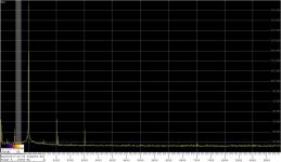
Here are two results with my latest configuration:
Regards,
Braca
P.S. With apologies,the correct value of R3 for the spectrum with lower THD is 133K, and not 82K as previously stated. I misread a color ring on the trim resistor parallel to the original R3.
- The FET is MMF4391, the shunt resistor R4 is 500R instead of 1K
- The voltage across the FET is 20mV,rms
- Reducing the R3 has a profound effect on the 2nd harmonic: with R3=150K (as delivered) the 2nd is 20dB higher than with R3=82K. However, reducing R3 by another 1K results in losing the control over the oscillator output voltage in that the latter then amounts to the full swing possible with the opamps used.
Regards,
Braca
P.S. With apologies,the correct value of R3 for the spectrum with lower THD is 133K, and not 82K as previously stated. I misread a color ring on the trim resistor parallel to the original R3.
Attachments

Last edited:
I first changed R12 (the right one) to 4.7Meg and got the output down to 3.5V. Its still referenced to the negative supply, that should be changed. Then played with R4. At 100 Ohms it won't settle, but at 180 Ohm it does settle. The bias on the Jfet is .5V with 1K, 2.5V with 180 Ohms. I can get H2 down (pot runs out of range) but H3 dominates. Signal across Jfet is 20 mV w/ 3.5V out. I'll need to do some tricks to see the AC on pin 6 of the TL071, its quite small.
I have not swapped any opamps yet. I know even a 5532 can do much better in these circumstances. I would like to get it to .001% or less with minimal changes before doing significant changes.
I have not swapped any opamps yet. I know even a 5532 can do much better in these circumstances. I would like to get it to .001% or less with minimal changes before doing significant changes.
demian... I was recently exploring the ShibaSoku AG16B generator circuits... without a schematic... which is how i blow up the AP front end BTW .... and saw a FET that I wondered if it ws the control fet.... it has the same pn -- 2SK30A.
Now, I think I will go into it again and play around with values used with the 2SK30A fet.
BTW -- the victor osc/gen and the AP 2722 shows the increased noise (green) of the Victor gen, as we know, and the 3H. How to lower the 3H?


THx-RNMarsh
Now, I think I will go into it again and play around with values used with the 2SK30A fet.
BTW -- the victor osc/gen and the AP 2722 shows the increased noise (green) of the Victor gen, as we know, and the 3H. How to lower the 3H?
THx-RNMarsh
The AG16 uses an analog multiplier. The FET is part of a sample and hold circuit. Why dont you take a good photo of the circuit so we can make a stab at reverse engineering. It. The amp sections are the same as the 725 input amp. The agc is more involved with sample and hold plus track and hold.
Sent from my LG-H811 using Tapatalk
Sent from my LG-H811 using Tapatalk
I noticed that Victors oscillator distortion changes with level. He has improved it. You could rework it or get a new one.
Sent from my LG-H811 using Tapatalk
Sent from my LG-H811 using Tapatalk
I had roughly reverseengineered AG16A circuit and shibasoku 550A oscillator which I got recently. 550A is basically 590A/R/AR phase shift oscillator but GPIB control.(but without CPU!)
Its amplitude detection circuit is more complex than AG16A but distortion factor is not so good and amplitude control loop oscillated in LTspice so it may be some error.
I also got junk 725B and repaired.I tested it and analysis function was NG. What failed was beckman7556CB ADC.I replaced it with BB ADC80 and modified surroundings bit then OK.
Attachments
Thanks for your work. I thought the AG16 had an analog multiplier. I can't find my photo's right now. The AGC is quite involved and an almost discrete sample and hold type circuit is very involved. I'll need some time to digest it. The model of the simple oscillator above doesn't quite work accurately since it stabilizes in less that 2 seconds, not the 15 seconds the simulator needs, which is typical of this stuff.
I first changed R12 (the right one) to 4.7Meg and got the output down to 3.5V. Its still referenced to the negative supply, that should be changed. Then played with R4. At 100 Ohms it won't settle, but at 180 Ohm it does settle. The bias on the Jfet is .5V with 1K, 2.5V with 180 Ohms. I can get H2 down (pot runs out of range) but H3 dominates. Signal across Jfet is 20 mV w/ 3.5V out. I'll need to do some tricks to see the AC on pin 6 of the TL071, its quite small.
I have not swapped any opamps yet. I know even a 5532 can do much better in these circumstances. I would like to get it to .001% or less with minimal changes before doing significant changes.
The topology of the SVO part of this oscillator is the same as in the one described by V. Katkov in
Audio Oscillator Distortion
which also includes a circuit analysis and simulation results.
With a more sophisticated control circuit, he claims a simulated THD of -141.6dB, and estimates -126dB in a built unit.
Regards,
Braca
Congratulations - the sterling performance of your 2722 finally returns! Here's the FFT of a 1Vrms 1kHz after an "extreme" notch treatment on the UPV. The signal was routed from the generator to the analyzer externally through a RG316 cable to simulate connection to a DUT and reveal any possible EMF/RFI weaknesses in the chain, With H2 and H3 both around -151dB, it looks OK to me.
Is RG316 preferable to RG174, and if so why?
Cheers,
Bob
https://www.pasternack.com
Biggest difference is temperature of operation, thus power rating because of the higher temp. As you see they are not all created equal, even for the same RG #. Usually the PTFE types feature silver plating. I recall that when I was at Motorola they used RG-400/U in the high end gear. We used a Wiltron return loss bridge setup to test our cable builds for return loss when we had critical measurements.
Generic Name RG174
Flex Type Flexible
Impedance 50 Ohm
Dielectric Type PE (LD)
Velocity of Propagation 66 %
Jacket Diameter 0.1 in
Jacket Material PVC
No. of Shields 1
Attenuation at 1 Ghz. 32 dB
Power, Max at 1 Ghz. 16 Watts
Frequency, Max 1,000 MHz
Max Operating Temperature 80 deg C
Center Conductor Type Stranded
Inner Conductor, Number of Strands 7
Coax Type Coax
Generic Name RG174 Type
Flex Type Flexible
Impedance 50 Ohm
Dielectric Type PE
Velocity of Propagation 66 %
Jacket Diameter 0.109 in
Jacket Material LSZH
No. of Shields 2
Attenuation at 1 Ghz. 25 dB
RF Shielding 90 dB
Frequency, Max 5 GHz
Max Operating Temperature 85 deg C
Center Conductor Type Solid
Inner Conductor, Number of Strands 1
Minimum Bend Radius, One Time 0.25 in
Minimum Bend Radius, Repeated 1 in
Coax Type Coax
Generic Name RG316
Flex Type Flexible
Impedance 50 Ohm
Dielectric Type PTFE
Velocity of Propagation 70 %
Jacket Diameter 0.114 in
Jacket Material FEP
No. of Shields 2
Attenuation at 1 Ghz. 26.1 dB
Power, Max at 1 Ghz. 160 Watts
Frequency, Max 3 GHz
Max Operating Temperature 200 deg C
Center Conductor Type Stranded
Inner Conductor, Number of Strands 7
Minimum Bend Radius, One Time 0
Generic Name RG316
Flex Type Flexible
Impedance 50 Ohm
Dielectric Type PTFE
Jacket Diameter 0.098 in
Jacket Material FEP
No. of Shields 1
Attenuation at 1 Ghz. 38 dB
Power, Max at 1 Ghz. 160 Watts
Frequency, Max 3 GHz
Center Conductor Type Stranded
Inner Conductor, Number of Strands 7
Coax Type Coax
Last edited:
Is RG316 preferable to RG174, and if so why?
Cheers,
Bob
The RG316 I have at hand works for this test, so that's what I used. I do not own any RG174 so cannot comment on which is preferable. From rasvas' post, it seems that the specs are somewhat in the RG316's favor but moot in AF range, and completely dependent on who made it.
Something i had explored was the accuracy of "sound card" type/based test systems. I found that below -100db the harmonics shown had no relationship to any reality.
recently, some have done a little better ---- -105-110dB is Ok.
Now I checked the relative numbers of three very expensive analyzers to see to what degree they agree. The three are Audio-Precision 2722, Panasonic 2277 (Matsushita Comm Ind) and ShibaSoku 725D. On each of these, i connected the QA401 FFT to their respective monitor output.
I used a generator which had 2H and 3H dominant. The only difference is found in the level of the 2H. of course, the 2H is closest to the notch circuits influence etc.
The levels are < -120dB r 1v rms
With the 7722, the 2H was +6db above 3H;
With the 725D, the 2H was +4dB above 3H;
With the AP, the 2H and 3H were same level.
However, the FFT displayed on the computer interface/screen... not at the monitor output via QA401.... showed the 2H to be much lower than the 3H. By -2 -4db
(2H seemed to go down with time -- heat related? drift? )
So, even with expensive analyzers, the numbers are not exactly the same, either. There is up to a 6dB or 10dB difference. But not wildly out of whack like cheap units. No ghost or added harmonics either. Of course, this is based on tests well below -100dB. Their limit in accuracy appears to start to become nuts below -130dB though fairly useful/consistent to -140 to -150dB.
The 2H seems to be most affected. higher fundamental freqs a little more so... null spreading/Q change etc?
I tend to think that the analyzer which gives the higher 2H is a more accurate unit..... tentatively.
THx-RNMarsh
Last edited:
- Home
- Design & Build
- Equipment & Tools
- Low-distortion Audio-range Oscillator