Davada,
I am so honored to be part of your SVO,
especially being included
in with SN: 0001
Thank you my
Northern Ice Brother.
😎🙂
-RNM
Davada,
I am so honored to be part of your SVO,
especially being included
in with SN: 0001
Thank you my
Northern Ice Brother.
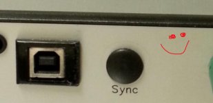
Oh I put the hole in the wrong place. Couldn't get the connector in.
It should have gone where the happy face is.
Last edited:
here is what might be termed a tracking caused error on the A-P 2722 analyzer --
The freq is 1KHz. The 2H and 3H is affected inversely.... but most affected is the 2H; The 2H level decreased at each freq change of 1% higher. At +5% change the 2Harmonics went back up.
View attachment 591635
THx-RNMarsh
Richard could it not be that a slightly different frequencies, the generator and/or analyzer have slightly different harmonic levels? Not necessarily a tracking error?
Jan
A notch filter is very sensitive to phase change closest to the center of the notch.
Move the frequency slightly increased or decreased and the phase can change. This may account for summation or subtraction between the generator and analyzer harmonics and consequently harmonic level.
RC generators are probably not all that phase/frequency stable at least not enough to avoid the above.
A notch filter is very sensitive to phase change closest to the center of the notch.
Move the frequency slightly increased or decreased and the phase can change. This may account for summation or subtraction between the generator and analyzer harmonics and consequently harmonic level.
RC generators are probably not all that phase/frequency stable at least not enough to avoid the above.
But would the notch not track with the freq changes?
But would the notch not track with the freq changes?
Implementation of notch filters vary. The R&S analyzers offer a notch filter tracking option called "Gen Track" which adjusts the center frequency of the filter to match the internal generator automatically. However, this option works only with the standard generator which is DAC-output driven. If the optional low-distortion analog generator is used, a reminder appears reminder to select manual tracking. Since the generator frequency does drift, the notch filter effect when it's right on and just a bit off can be obvious.
But would the notch not track with the freq changes?
Depends on the design, If the control is too fast it can modulate the phase/frequency.
The control in the 339A for example tracks the average. If the changes are fast in the generator the notch controller just sees the average. Then there is the TC of the integrator in the control loop as well.
Just like the compensation in a FB amplifier a control loop has to stable within the loop phase response. Too fast a response and loop is unstable.
Also in some cases like the 725 the notch is open loop and moves in discrete steps set by the frequency counter so there will be some small issues as the fundamental changes. I don't know if the AP is open loop or has a servo. Again, the best way to know what is happening is testing.
OK, clear, thanks guys!
My dScope is digital based, both gen and analyzer so appears to track pretty well, but will check next time I fire it up.
Jan
My dScope is digital based, both gen and analyzer so appears to track pretty well, but will check next time I fire it up.
Jan
Without delving deeper into the design(s), there are many possible reasons for the harmonics to shift and be inaccurate; drift, clock freq drift, freq tracking and null adjust sensitivity, phase shifts/changes, etc etc. I just like to show that the readings on a quick one-take may not be what you think it is.... especially at very low signal levels.
After many hours of being ON, the AP seems to loose the 2H ..... for what ever reason.... Would make your DUT seem to have no 2H .

Then as before when the freq source is shifted a small amount higher.... the first harmonic detected starts to drop in level and the 3H starts to rise.
Shift the freq enough and - what? -- a 2H appears !!

I'll check this against the Monitor output hooked to a QA401 because something seems to be going on with the post-processing.
For the inexpensive "sound card" type based analyzers, I would carefully look at the accuracy below -100-105dB before taking the data as the truth and nothing but the truth.
THx-RNMarsh
After many hours of being ON, the AP seems to loose the 2H ..... for what ever reason.... Would make your DUT seem to have no 2H .
Then as before when the freq source is shifted a small amount higher.... the first harmonic detected starts to drop in level and the 3H starts to rise.
Shift the freq enough and - what? -- a 2H appears !!
I'll check this against the Monitor output hooked to a QA401 because something seems to be going on with the post-processing.
For the inexpensive "sound card" type based analyzers, I would carefully look at the accuracy below -100-105dB before taking the data as the truth and nothing but the truth.
THx-RNMarsh
Last edited:
This is all very good and interesting stuff. Richard, CiII, how would you set up your R&S for
the measurements? I can try and duplicate what richard did and see how it compares.
We have to remember that Demian would use 997 Hz for running tests and gave some
detail. As I mention somewhere here that is an important and now I recall why.
We use 997 Hz because it is a Prime Number. So for FFT measurements, bins,
drifts, harmonics presented calculated etc., by definition a prime number can only have two factors, one and itself. 997 Hz may help resolve some issues we've (we meaning you) observed. We can only repete the measurements and observe if there is a difference.
Richard, would you mind redoing these FFT plots at 997 Hz used? You are snowed
in up there in the California foothills right? I hope you have plenty of food stored up,
I mean we don't Donner Party moment in Cool, California do we? 🙂
Seriously though, this might actually be an important study to actually verify the differences,
if any as we have questions about measurements, plots, and variation.
I recall when I was at a seminar that Dr. Edwards Deming was presenting and
he was discussion variation is an important part in every system and it's import
and to recognize it. A managers duty was to separate system variation from
externalizes, because to affect change system variation can only be addressed
by changing the system itself.
When plotted using d(x) f(x) calculus max min graphs...being close to the max
or being close to the min of the system was good enough. Because all that effort
will affect little change because we are close to being at the 90 degree tangent point.
Think of a sine wave...at the max Vpp point its 90 degrees. The slope of the tangent
changes very little on either side of that line. I'm talking close to it here not
far away. So we (meaning y'all) might actually be at that area. Just putting
it out there to consider.
Y'all are a smart guys. I always like hanging out and learning from y'all.
Next week I go back to school, I get to learn about solid state devices
using the electron flow method. 🙂
For some reason I woke this morning with a head ache...when I looked in
the mirror I saw what looked like drill walk marks on it. Hmmm Davada,
why might I have those?
If I can figure out how to get the Rohde and Schwarz UPD connected to an
external monitor and use either a parallel port or serial port to the computer
I could send info to QA400. I am QA401less 🙁.
Are the QAs still unable to interface to ARTA?
Cheers,
Last edited:
Oh come on now Chris, don't be bottom feeding here. 
That reminds me that I have to open it up and change batteries.
and figure out how to not have it lose it's settings.
Cheers,
That reminds me that I have to open it up and change batteries.
and figure out how to not have it lose it's settings.
Cheers,
Hi Sync,
Remember, supply another power source, same voltage through a 10 K resistor. Then swap out the batteries.
I'll do it if you want! 🙂
-Chris
Remember, supply another power source, same voltage through a 10 K resistor. Then swap out the batteries.
I'll do it if you want! 🙂
-Chris
CiII, how would you set up your R&S for
the measurements?
The R&S used for the plot I posted is from a UPV, which is Windows-based. My belief is that its firmware evolved more in the direction of the AP2700 - adding even more functional blocks than the UPD/UPL that came before it. Moreover, on the UPL and UPV, more notch filters can be user-defined, in addition to the 2 R&S supplied - one analog and one digital.
These filters are selected as an analyzer parameter for the DSPs post-ADC. The UPV goes one step further and allows the same filters to be used with the generator, further conditioning the signal before the DUT. I am pretty sure the UPD allows a user-definable notch filter but am not sure whether it can be applied elsewhere other than in the analyzer. The UPL cannot.
Since the user-defined notch filter is digital and is brutally precise, it's important to use the digital generator, and use "Gen Track" as the Meas Time parameter to have the center frequency land in exactly the right place for maximum effect. The rest should be vanilla.
Good luck.
Our R&S UPD has a 1KHz THD residual of about -130dB (low distortion analog oscillator plus the analyzer). THD+N @1KHz is about -116dB, both in a 20KHz bandwidth, no extra filters, 5Vpeak output.
At 20KHz, the THD residual is -112dB while THD+N is -103dB, both in a 100KHz bandwidth, everything else as above.
Switching to 20KHz requires switching the analyzer to 100KHz (there are three analyzers, 22.1KHz, 100KHz and 300KHz) and I suppose much of the difference is from the analyzer rather than from the oscillator. The same 1KHz with the 100KHz analyzer (100KHz bandwidth) gives a residual THD of -120dB and THD+N of -108dB.
This is all very good and interesting stuff. Richard, CiII, how would you set up your R&S for
the measurements? I can try and duplicate what richard did and see how it compares.
We have to remember that Demian would use 997 Hz for running tests and gave some
detail. As I mention somewhere here that is an important and now I recall why.
We use 997 Hz because it is a Prime Number. So for FFT measurements, bins,
drifts, harmonics presented calculated etc., by definition a prime number can only have two factors, one and itself. 997 Hz may help resolve some issues we've (we meaning you) observed. We can only repete the measurements and observe if there is a difference.
Richard, would you mind redoing these FFT plots at 997 Hz used? You are snowed
in up there in the California foothills right? I hope you have plenty of food stored up,
I mean we don't Donner Party moment in Cool, California do we? 🙂
Seriously though, this might actually be an important study to actually verify the differences,
if any as we have questions about measurements, plots, and variation.
I recall when I was at a seminar that Dr. Edwards Deming was presenting and
he was discussion variation is an important part in every system and it's import
and to recognize it. A managers duty was to separate system variation from
externalizes, because to affect change system variation can only be addressed
by changing the system itself.
When plotted using d(x) f(x) calculus max min graphs...being close to the max
or being close to the min of the system was good enough. Because all that effort
will affect little change because we are close to being at the 90 degree tangent point.
Think of a sine wave...at the max Vpp point its 90 degrees. The slope of the tangent
changes very little on either side of that line. I'm talking close to it here not
far away. So we (meaning y'all) might actually be at that area. Just putting
it out there to consider.
Y'all are a smart guys. I always like hanging out and learning from y'all.
Next week I go back to school, I get to learn about solid state devices
using the electron flow method. 🙂
For some reason I woke this morning with a head ache...when I looked in
the mirror I saw what looked like drill walk marks on it. Hmmm Davada,
why might I have those?
If I can figure out how to get the Rohde and Schwarz UPD connected to an
external monitor and use either a parallel port or serial port to the computer
I could send info to QA400. I am QA401less 🙁.
Are the QAs still unable to interface to ARTA?
Cheers,
Just remember the schematic symbols are still pointing in the current flow direction.
It was too great a transition to reverse the arrows on transistor and diode without confusion with viewing legacy schematics. So it was just left as is.
"I saw what looked like drill walk marks on it." Stop taking your drill to bed with you.
Last edited:
The issues discussed with analyzers are further complicated when we read out with FFT. Now we have the issues with distribution of harmonic power through adjacent bins.
Richard this can be avoided by using a spectrum analyzer. You have at least one I think.
Can you repeat the measurements using an SA instead of the QA40x.
Richard this can be avoided by using a spectrum analyzer. You have at least one I think.
Can you repeat the measurements using an SA instead of the QA40x.
997 Hz is specifically for ADC's and DAC's. By not fitting in a bin neatly it exercizes every bit of the DAC/ADC. if you are on a nice submultiple or divide of the sample rate you may end up skipping some bits in the translation and get an unreasonable false result.
Not relevant for an analog analyzer. Also when looking at the output of an analog analyzer. Even really good swept analyzers don't have the resolution of digital analyzers. Most of the newer SA's are digital in the final filters so you get the best (and worst) of both. I have a Tek 7L5 (3 actually) and also a Quantech Wave analyzer (2449?) which work well but just don't have that resolution (and are really slow). Richard has an Anritsu which works similarly to the Tek. I do use mine to look at out of band stuff with DAC's and also for tuning/tweaking FM sources for what its worth.
Not relevant for an analog analyzer. Also when looking at the output of an analog analyzer. Even really good swept analyzers don't have the resolution of digital analyzers. Most of the newer SA's are digital in the final filters so you get the best (and worst) of both. I have a Tek 7L5 (3 actually) and also a Quantech Wave analyzer (2449?) which work well but just don't have that resolution (and are really slow). Richard has an Anritsu which works similarly to the Tek. I do use mine to look at out of band stuff with DAC's and also for tuning/tweaking FM sources for what its worth.
- Home
- Design & Build
- Equipment & Tools
- Low-distortion Audio-range Oscillator