Didn't we discuss, some time back by e-mail, a simple means (pure C or a RC network in parallel with the input resistor of the inverting stage) to control the Q enhancing effect, as done in the SG505 and System One? At the time of writing, my oscillator design has a steady-state control voltage range of less than +/-1 V (of a maximum of about +/-12 V) from 10 Hz to 100 kHz, and that's with very low multiplier authority.
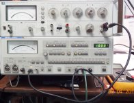
Not sure I follow. You're measuring the output of the modified 339A oscillator section by feeding it to the analyzer section of the 339A, and then the residual monitor output to the QA400?
Samuel
Hi Samuel,
The Q enhancing is in there. I simply run out of proportion voltage range over 90 kHz.
I can get to 90kHz just fine but I don't want to increase gain any more than it is.
I can let the integrator take it right up to 100kHz but the AGC is unstable without full proportional authority. Keep in mind our multipliers are quite bit different and so are the AGC's. I guessing you don't have the long TC of a lamp to deal with. Once the integrator has been steered to the control point and the SVO has settled the steady-state control voltage range is +/- a few mV.
I haven't seen your complete circuit so I can't really comment on it.
Not sure I follow. You're measuring the output of the modified 339A oscillator section by feeding it to the analyzer section of the 339A, and then the residual monitor output to the QA400?
Samuel
yes.
We spent quit some time on the osc section and the analyzer section. Then went on to other makes and models and FFT.
Thx-RNMarsh
The Q enhancing is in there. I simply run out of proportion voltage range over 90 kHz. I can get to 90 kHz just fine but I don't want to increase gain any more than it is.
I can let the integrator take it right up to 100 kHz but the AGC is unstable without full proportional authority. Keep in mind our multipliers are quite bit different and so are the AGC's. I guessing you don't have the long TC of a lamp to deal with. Once the integrator has been steered to the control point and the SVO has settled the steady-state control voltage range is +/- a few mV.
Not sure I follow--is the leveling loop saturating (i.e. its authority is not large enough), or is there a stability issue with the leveling loop (i.e. it oscillates)? I've seen and cured both.
Samuel
Richard:
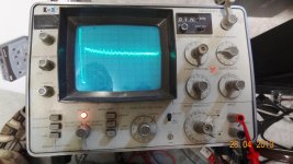
The plot indicated that the fundamental has been nulled to -150 dB. That is exceptional under the best of conditions. Victor has mentioned the use of a marker to verify the distortion amplitudes. I think it makes sense when these are such low levels.
The plot indicated that the fundamental has been nulled to -150 dB. That is exceptional under the best of conditions. Victor has mentioned the use of a marker to verify the distortion amplitudes. I think it makes sense when these are such low levels.
Richard:
The plot indicated that the fundamental has been nulled to -150 dB. That is exceptional under the best of conditions. Victor has mentioned the use of a marker to verify the distortion amplitudes. I think it makes sense when these are such low levels.
Thats about right, i think. davada's did as well, i believe.
I took the modified HP 339A back over to the ShibaSoku 725 analyzer and remeasured it and it agrees within +/- 3dB for 2h and 3H. Then i retuned the 339A for just one freq (1KHz) and was able to null the harmonics below the residual of the 725 and cant see any harmonics any more -- into the noise of the 725 floor/system.... even gone when looking at the monitor output with the HP spectrum analyzer. But typically it is then much worse at 10KHz. So, I had left it at a compromise tune... all harmonics from 100-10KHz are below .0001% thd.
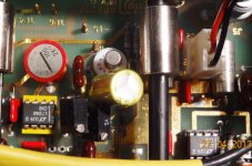
Of course I have replaced just about every IC and part in the signal path and also in the analyzer and placed trimmers where there were fixed R's. Etc.
Thx-RNmarsh
Last edited:
Thats about right, i think. davada's did as well, i believe.
I took the modified HP 339A back over to the ShibaSoku 725 analyzer and remeasured it and it agrees within +/- 3dB for 2h and 3H. Then i retuned the 339A for just one freq (1KHz) and was able to null the harmonics below the residual of the 725 and cant see any harmonics any more -- into the noise of the 725 floor/system.... even gone when looking at the monitor output with the HP spectrum analyzer. But typically it is then much worse at 10KHz. So, I had left it at a compromise tune... all harmonics from 100-10KHz are below .0001% thd.
Of course I have replaced just about every IC and part in the signal path and also in the analyzer and placed trimmers where there were fixed R's. Etc.
Thx-RNmarsh
Rick I could never get the null much below -125dB. maybe -130dB for brief amount of time but then it would climb back up to -120dB or so and settle there. I've never measured the 339a distortions that low. If one harmonic dropped it was at the expense of the other increasing between 2nd and 3rd. I could get either down lower than -130dB and that's about what others measure as well.
Cheers,
THD of -125-130dB is par for the upgrades. And that is very, very good. That is the THD I get typically. I trim three R's.... The series R to the jFET gate, the shunt R from gate to drain and the agc. The individual harmonics from the 725 show lower levels than THD, of course. But the caps and other parts have to be selected also for lowest distortion and cleaned contacts etc. etc. etc. I'm using LT1468 in most places.
Its been On all this time and I checked the THD and it hasnt changed. Probably a fortuitous combination of phases and settings and parts for one frequency.... which is why i started looking at other oscillators which can be tuned to deep null over a wide range of freqs.
Thx-RNMarsh
Its been On all this time and I checked the THD and it hasnt changed. Probably a fortuitous combination of phases and settings and parts for one frequency.... which is why i started looking at other oscillators which can be tuned to deep null over a wide range of freqs.
Thx-RNMarsh
Last edited:
What did you do on the analyzer side to get the null that low and the harmonics that low?
In general, replaced all caps with film and 105C NP types and all opamps with various makes and models that worked best in each location/function and 20-turn trimmers in place of single turn etc etc.
Dick Moore has done this before we did with similar results in THD from a 339A. www.moorepage.net
But -150dB does seem like a lot.
-RNM
Last edited:
BTW - dick moore said on his site that the 339A had a null depth of greater than -110dB.
With some work that number can be and has been improved.
-Thx RNMarsh
With some work that number can be and has been improved.
-Thx RNMarsh
40 dB is a lot of improvement. Setting the null would be very very touchy at -150 dB.
You are assuming. Didnt know what the number actually was... just that it was more than -110dB. yes, it was a bit touchy but with a fine trim with 28 turns it isnt so touchy as you think. With the stock single turn it is Very touchy and unstable.
I just plugged the qa400 into the distortion monitor port and that is what it said. i can double check someday later. Even if somehow the system was off by 10 or 20dB (!), it would still be a very deep null number. But then the distortion numbers would be that far off as well. The null is VERY deep on mine.
[ for modders -- the opamp for the Notch Amp U3 is a OPA1641]
Thx-RNMarsh
Last edited:
I was reading back from the QA400. if 0 dB on the scale was -80dB and the center of the null is -70dB on the display, that's -150dB. My 725 only gets to about -130 dB on the monitor output at best. I have never got much past -120 dB with any of my other analyzers and then any variations in anything knock it all askew again.
Also My Shibasoku is very sensitive to emi and rfi. If my Metcal iron is on the distortion indication goes up 10-20 dB. I would not be surprised if other high resolution systems are sensitive as well.
Consistent fundamental rejection (particularly in the presence of noise and interference) much beyond 120 dB probably requires a cascade of at least two notch filters (as used in the System One and apparently also the AD725D). See US patent 4563652 A.
Samuel
Samuel
My understanding with the 725 is that it used 3 notch filters and reached -160dB.
I just thought of something to double check.... get back to you later... might explain the numbers... .
I also have an e-Mu 0204 and today a e-MU 0404 arrived. Going to go play and mod those now.
-RNM
I just thought of something to double check.... get back to you later... might explain the numbers... .
I also have an e-Mu 0204 and today a e-MU 0404 arrived. Going to go play and mod those now.
-RNM
Last edited:
Cool--now the question is how well this keeps up at other frequencies, and with the 3rd harmonic. Can you do a graph of 2nd/3rd harmonic vs. frequency?
Samuel
Samuel
- Home
- Design & Build
- Equipment & Tools
- Low-distortion Audio-range Oscillator


