Google calc says 3.16227766e-9
I can do that with a "float" variable in C 🙂 which has 17 significant digits, 4 bytes.
A "double" has 64 bits (8 bytes).
But I guess a deeper analysis is needed.
I can do that with a "float" variable in C 🙂 which has 17 significant digits, 4 bytes.
A "double" has 64 bits (8 bytes).
But I guess a deeper analysis is needed.
That -170dBr is referred to a certain number. It does not mean that there has been a -170dB calculation. See my post above.
But if you want you can calculate how much (little) -170dB is; your Windows calculator can do that {10^(-170/20)}. Then you know how many digits are needed.
Jan
I did not mean that float32 could not transfer -170dBFs levels, just that long 8M FFT in float32 on precise digitally-generated 24bit signal as performed by jaaa produces artefacts up to that level. I do not know if the artefacts are really produced by the FFT but likely so as FFT is the only frequency-dependent processing in that analyzer.
Very likely not important in this level.
Very likely not important in this level.
Lets do some mental calculations then, I also want to understand it. Start with 1V to keep it simple. Through the twin-tee gets you -50dBV.
Next, the AP autoranger applies say 60dB gain, which it remembers as a correction to be applied later. The fundamental signal is now 3V.
Next comes the AP notch filter. I don't know it's performance, but let us say -110dB; that seems a reasonable assumption looking at many 'normal' AP 2722 spectra. That puts the fundamental at 10uV.
Edit: that notch is even better apparently ..
Still... some questions...
Let's assume the oscillator has fundamental 0dBV, H2 at -150dBV
Oscillator -> external passive notch filter -> fundamental at -50dBV, H2 at -200dBV
AP 60dB active gain -> fundamental at 10dBV,DUT H2 at -140dBV. What are internal harmonics for the AP active gain stage for fundamental at quite large level of 10dBV? IMO at least some -120dBV (i.e. -130dB against the fundamental) - already overriding the DUT (oscillator) harmonics.
Subsequent -130dB notch (active?) - is it really that steep that it does not affect H2, H3 while not creating any harmonics itself?
If it is so steep, we should see the AP harmonics combined with the oscillator harmonics, yet the chart shows nothing at -150dBr = -152dBV
If it is not so steep, the AP notch hides the harmonics, including the unknown DUT ones.
Or maybe it is completely different, I really do not know. I just do not see how that chart with fundamental at -170dBr = 172dBV was reached without seriously changing the original DUT H2 and H3 frequencies somewhere along the path. Just asking...
Notch only takes out fundamental.
Much less at H2.
Otherwise it is not a notch. Or very poor one.
Patrick
Much less at H2.
Otherwise it is not a notch. Or very poor one.
Patrick
float is a 32 bit IEEE 754 single precision Floating Point Number, 1 bit for the sign, (8 bits for the exponent, and 23* for the value), i.e. float has 7 decimal digits of precision.Google calc says 3.16227766e-9
I can do that with a "float" variable in C 🙂 which has 17 significant digits, 4 bytes.
[...]
I know. But I am asking by how much for a -130dB notch, with what internal distortion (if active), and where is the remaining AP internal distortion if the notch does not attenuate it and the input signal is >0dBV after input gain in the AP autoranger. Maybe I am asking wrong, I may be missing something, again, quite common. Thanks.
Notch only takes out fundamental.
Much less at H2.
Otherwise it is not a notch. Or very poor one.
Patrick
Exactly. The 2nd is attenuated 8dB by my notch and I correct that with the setting of the ref. The 3rd is attenuated 4dB so after the correction by 8dB for the 2nd, the 3rd is shown 4dB higher than it actually is.
I expect similar correction going on inside the AP for its notch but I don't know about that.
Don't forget that with this almost perfect oscillator, the main source of the distortion is the ADC of the analyzer. By using a passive notch, the dynamic range is much reduced. Instead of 150dB (1V fundamental and -150dB harmonics) it is now about 100dB (fundamental cut down 50dB). And the AP circuits can be expected to handle 100dB range signals without adding its own harmonics, meaning its own distortion is (far) below -100dB.
Jan
Last edited:
Float is probably not a good word to use. Better to use Single-precision floating-point format as per IEE 754.
float is a 32 bit IEEE 754 single precision Floating Point Number, 1 bit for the sign, (8 bits for the exponent, and 23* for the value), i.e. float has 7 decimal digits of precision.
I think Edmond used float as the variable type in for instance C++. It is the definition, so perfectly good use.
I have a few hairs here, can I bring them to you to split? ;-)
Jan
I have a few hairs here, can I bring them to you to split? ;-)
Jan
Nothing probably, I just haven't tried that ;-)
Need to keep some tasks for the rest of this 1 year lock-up ;-)
Jan
Need to keep some tasks for the rest of this 1 year lock-up ;-)
Jan
I've got good experience with an adjustable passive notch filter with a depth of at least -90dB and Groner's or Wurcer's LNA, both with 60dB gain.
Data acquisition with an external FireWire 400 audio interface.
Data acquisition with an external FireWire 400 audio interface.
Stop it or we just loose jan.didden (somewere under -200dB)! 🙂I'm using long doubles (80bits). 🙂
I thing I get the calculation of what was going on (isch):
* oscillator
assumed 1V fundamental, -150dBV H2
* twin-T notch -50dB, -8dB at H2
-50dBV fundamental, -158dBV H2
* gain 60dB (with gain adjustment later on)
10dBV fundamental, -98dBV H2 + distortion of the active gain stage (e.g. -130dBV which is negligible compared to the -98dBV of H2 - ignored)
* AP notch -120dB, no attenuation at H2
- 110dBV fundamental, -98dBV H2
* AD Conversion - negligible distortion due to tiny fundamental - ignored
* gain adjustment -60dBV for final displayed values
-170dBV fundamental, -158 dBV H2
The measured chart shows noise at -150dBV, the H2 is anywhere below that level. I assume that noise comes from the 60dB gain stage.
-150dBV on the display would correspond to -142dBV H2 of the oscillator (considering the AP notch of -120dB with no H2 attenuation (unlikely but possible)). I.e. any oscillator H2 below -142dBV would get below the noise as analyzed by the given FFT length.
Now I am happy, thanks for the patience 🙂
Last edited:
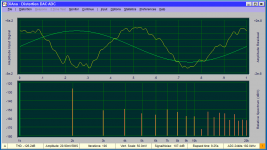
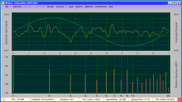
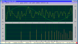
Here are some measurements of my first gen Victor oscillator. I has the original LME49720 and none of the more recent tweaks.
This is using ta Victor oscillator (first gen) + B&K 1607 tunable notch filter + RTX. The first measurement is direct into the RTX at a pretty optimal level and indicative of what you can get with possibly the best ADC implementation today. The second is with the B&K notch which has a 70 dB insertion loss at the fundamental (994.38Hz) 10 dB at 1994 Hz and 6 dB at 2988 Hz. in the "frequency" mode. In the "distortion" mode its 74 dB at the fundamental 21 dB at 1994 20.5 dB at 2988 KHz.
For the frequency mode you need to add 70 dB + correction for the harmonics, for the distortion mode you are within 2 dB by just adding 54 dB.
DiAna does a great job of avoiding noise and spuriii which there will be a lot of below -140 dB. The signal in to the RTX was at 500 uV approx.
Attachments
Hi Demian,
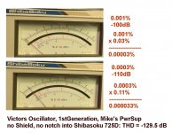
That's alright. My 1st gen Victor's oscillator THD is -129.5
as best as I can determine. No shielding, no notch, open
frame with Mikey's power supply. There is no difference
that I can determine yet between Mikey's board with
capacitor multiplier with 2 resistors or diode FET.
Here are my last measurements for confirmation:
Cheers,
Attachments
- Home
- Design & Build
- Equipment & Tools
- Low-distortion Audio-range Oscillator