Motorized pots? It would add enormous complexity to save what? It's not like one needs a production line instrument.
Enormous complexity? There is probably an easy way.
BTW - I had one of them already... Cordell magnifier.
-Richard
Last edited:
Enormous complexity? There is probably an easy way.
Why bother? Please make a suggestion for tuning 4 pots that interact. We had a customer that wanted to make an auto-convergence system with AD815's driving coils around and old CRT based display, thankfully flat panels killed that.
Well, if you use a 20 turn pot, you wont need the trims. So, now we are down to just 2 pots. Built around a comparator circuitry to drive pots to find zero volt diff.
Conceptually. The details are for the bug guys. The specialists.
But why bother? If measuring really really low levels the parts and thermals of amp et al will cause you to manually retune from time to time for best diff cancellation.... auto tune then is nicer.
-Richard
Conceptually. The details are for the bug guys. The specialists.
But why bother? If measuring really really low levels the parts and thermals of amp et al will cause you to manually retune from time to time for best diff cancellation.... auto tune then is nicer.
-Richard
Last edited:
Everything is easy for the person who doesn't have to do it himself ...
Jan
Management, have you ever tried to push a chain?
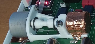
Yes, most likely nothing complicated. A $2 10-turn 5K pot attenuator adjusts to +/- 0.002dB level with a $2 geared stepper, resolution limited by number of wire wounds per revolution inside the pot. Several concurrently running steppers easily controlled by $2 arduino. Works very good, would work good in this device too.
Yes, most likely nothing complicated. A $2 10-turn 5K pot attenuator adjusts to +/- 0.002dB level with a $2 geared stepper, resolution limited by number of wire wounds per revolution inside the pot. Several concurrently running steppers easily controlled by $2 arduino. Works very good, would work good in this device too.
I assume Bob included a coarse and fine control for a reason. Besides unless someone steps forward and provides a finished solution including BOM with part numbers all the mechanicals and code IME nobody would take it on. There are numerous minor issues being glossed over.
I had a tech that would look at an article and read the schematic and say nobody is going to build this and it was usually true.
I assume Bob included a coarse and fine control for a reason.
I have been through that too. Practical manual control requires coarse and fine elements, because manual adjustment with a single high-resolution control is tedious and boring. But having 2400 steps per revolution controlled automatically may create a different situation.
Should anyone go for it, I offer STLs for the stepper-pot assembly including the axes coupler. Snap rings are 30pcs per dollar in local hardware store.
Attachments
voltage controlled capacitance
Something I designed many years ago. ( I used it when experimenting with constant switching frequency in Class D amps and clipping behaviour)
Can also be used in the frequenzy compensation in a class AB amp.
It is an open collector circuit so you have to "isolate" the C by using a Cap on each side.
Stein
Attachments
I assume Bob included a coarse and fine control for a reason. Besides unless someone steps forward and provides a finished solution including BOM with part numbers all the mechanicals and code IME nobody would take it on.
.
Well, you did ask. And, you got several replies already. If you dont want to know, then dont ask. I am reminded of the HP332 thd analyzer.... manual coarse and fine tune with pots. Was always drifting off null. Next version? Auto null tuning.
And, it wasnt with motorized pots. HP334.
THx-RNMarsh
Last edited:
Should anyone go for it, I offer STLs for the stepper-pot assembly including the axes coupler
Pavel, what's an STL?
BTW IF I would build something like that it would use something like an NLS-32. They work great in my tracking notch filter. No digital control required as you can use a completely analog control chain.
That tracking notch is almost ready, the prototype needs to be tested on residual distortion, need to make some time for it.
Jan
STL is a standard model exchange format used in 3D printing, basically a detailed triangular mesh. Millions are available for download, e.g. Thingiverse - Digital Designs for Physical Objects
If a vactrol is suitable for the given task, of course no reason to consider any mechanical solution. I need very low distortion and resistance range in single kiloohms for reasonable price, hence the stepper/pot choice.
If a vactrol is suitable for the given task, of course no reason to consider any mechanical solution. I need very low distortion and resistance range in single kiloohms for reasonable price, hence the stepper/pot choice.
It depends a lot on the control range. For instance, in my tracking notch, the nominal control element is around 8k, and the opto's are around 200R +/-50R. That is the range where the opto, with <50mV across it, has very low distortion, which is also attenuated by the 200R to 8k ratio.
But if you need higher resistance and/or more signal across the opto, extremely low distortion is out of reach.
It's all engineering ;-)
BTW It would be nice if I could 3D print my own IC's!
Jan
But if you need higher resistance and/or more signal across the opto, extremely low distortion is out of reach.
It's all engineering ;-)
BTW It would be nice if I could 3D print my own IC's!
Jan
Last edited:
Yeah, I need very large range (0 to -30dB).
The 3D printed custom ICs are to come in near future 3D Printing of Integrated Circuits: Four Trends You Need to Know | Design News
For now I would be just happy if I could print out plastic enclosures at surface quality of molded plastic, price single dollars per piece, and time under one hour. Still long way to go 🙂 Sorry for the offtopic.
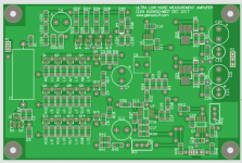
The complete schematics of Glen's analyzer can be found here:
An Audio T.H.D. Analyser
There are also links to the Gerber files, but they are dysfunctional.
I hope not to have broken any law by posting the above link.
Regards,
Braca
Glen is a seriously capable designer - pity he left. I’ve hunted around on the web but can find no trace of him. Thanks for digging this up BTW. I’ve book marked it - there’s a lot to learn reading through it.
To your point Scott - agree this forum can get frustrating at times. I also left for a while because of the behavior of some.
Hi Bonsai,
I think you might be able to find him on the EEVblog Electronics Community Forum - Index
Last place I saw him post.
Mogens
I think you might be able to find him on the EEVblog Electronics Community Forum - Index
Last place I saw him post.
Mogens
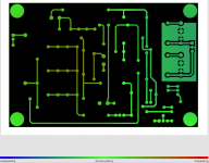
The PCB Gerber set throws an error. Apparently Glen designed it for his outline milling machine. There seem to be non-standard Gerber files. I'll see if I can rescue it.
Edit: you need to turn off 'controlled impedance' in your CAD as that was set to ON but is not available on 2-layer boards. After that, no errors. Is manufacturable, with some possible overplating on the bottom side due to the large difference in copper cover between the top and bottom layers..
Jan
Edit: you need to turn off 'controlled impedance' in your CAD as that was set to ON but is not available on 2-layer boards. After that, no errors. Is manufacturable, with some possible overplating on the bottom side due to the large difference in copper cover between the top and bottom layers..
Jan
Attachments
Last edited:
- Home
- Design & Build
- Equipment & Tools
- Low-distortion Audio-range Oscillator