A method which does not use a notch filter is a note by TI App EE
"New Technique Accurately Measures LF Distortion to below -130 dbc Levels" by Xavier Ramus.
THx-RNMarsh
"New Technique Accurately Measures LF Distortion to below -130 dbc Levels" by Xavier Ramus.
THx-RNMarsh
Last edited:
A method which does not use a notch filter is a note by TI App EE
"New Technique Accurately Measures LF Distortion to below -130 dbc Levels" by Xavier Ramus.
This is aimed at high frequency A/D drivers, no plots below 1kHz here and it focuses on performance to several MHz. I think it is also inverting only and requires device dependent fixturing. Again no help in measuring an oscillator anyway.
I can't find Bob's distortion magnifier article, it can do -140dB at audio frequencies and its not that hard to build, also no help on the oscillator.
Last edited:
Glen Kleinschmidt had a nice evolution of Bob’s distortion meter. It was up on tne web, but he seems to have gone underground. The specs IIRC were very good.
Glen Kleinschmidt had a nice evolution of Bob’s distortion meter. It was up on tne web, but he seems to have gone underground. The specs IIRC were very good.
IIRC Glen also had a very nice SVO. Glen left in disgust along with a few others a long time ago over that which still keeps on rolling to this day
Last edited:
The complete schematics of Glen's analyzer can be found here:
An Audio T.H.D. Analyser
There are also links to the Gerber files, but they are dysfunctional.
I hope not to have broken any law by posting the above link.
Regards,
Braca
An Audio T.H.D. Analyser
There are also links to the Gerber files, but they are dysfunctional.
I hope not to have broken any law by posting the above link.
Regards,
Braca
This is aimed at high frequency A/D drivers, no plots below 1kHz here and it focuses on performance to several MHz. I think it is also inverting only and requires device dependent fixturing. Again no help in measuring an oscillator anyway.
No. It will go much lower in freq. Read all the way down.
I thought it Might have useful design idea for someone here. It doesnt use a notch filter.
Take the concept and apply/mod it as needed?
THx-RNMarsh
Last edited:
VK-2 Distortion Meter
with auto-null tuning...
and
Ultra Low Distortion Test Equipment Klirrfaktor Messgerät
THx-RNMarsh
with auto-null tuning...
and
Ultra Low Distortion Test Equipment Klirrfaktor Messgerät
THx-RNMarsh
Last edited:
Bootstrapped 2T & positive feedback? Again? Starting from about page 852, a few links were posted on a topic. For example,VK-2 Distortion Meter
with auto-null tuning...
and
Ultra Low Distortion Test Equipment Klirrfaktor Messgerät
THx-RNMarsh
Harmonic Distortion in a Class of
Linear Active Filter Networks
PETER J. BILLAM
Filtek A.G., Biel, Switzerland
Journal of the Audio Engineering Society, June 1978, Volume 26 Number 6, pp.426-429
Question: in "New Technique Accurately Measures Low-Frequency Distortion To <-130 dBc Levels
by Xavier Ramus," there is a component "programmable delay" - what the hell is it?
Bootstrapped 2T & positive feedback? Again? Starting from about page 852, a few links were posted on a topic. For example,
Harmonic Distortion in a Class of
Linear Active Filter Networks
PETER J. BILLAM
Filtek A.G., Biel, Switzerland
Journal of the Audio Engineering Society, June 1978, Volume 26 Number 6, pp.426-429
Question: in "New Technique Accurately Measures Low-Frequency Distortion To <-130 dBc Levels
by Xavier Ramus," there is a component "programmable delay" - what the hell is it?
haha I dont know.
I stopped trying to get ultra low sources and test gear some time ago. But, here there are many still hanging in for a DIY project i suppose which will get one a lot lower than a sound card.
My approach was to take a used oldie but goodie test equipment and rework it. Everything is there... chassis, PS etc. I started with the HP339A. Source and analyzer together. And, an FFT (QA401) on the monitor port gave added utility. Before that were many sound card and their mods and software packages. At about -120 seems to hit a wall. From there can add LPF and notch. It gets a lot more complicated and difficult to get lower. Fortunately, -120 is good for most things.... it is readily avail both hardware and software.
With better equipment, I soon learned I could measure thd/harmonics lower than the sources available. I went searching on e-bay and found Victors oscillators. Which led to David doing a variable freq version. However, I can still measure below those sources. Barely.
The rest since is an engineering challenge. 🙂 -140, -150, -160 -180. ??
For myself, at this point in time, LPF and notch filters get the remaining residuals.
THx-RNMarsh
Last edited:
I can't find Bob's distortion magnifier article, it can do -140dB at audio frequencies and its not that hard to build, also no help on the oscillator.
Attachments
Should be a way to auto-zero-null-subtract and not have to manually tune for a minimum.
??
THx-RNMarsh
??
THx-RNMarsh
New set of results for the concept "LP filter at the output of an oscillator".
The details of the setup are here:
Low-distortion Audio-range Oscillator
so I'm only presenting the changes.
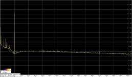
First I tweaked the oscillator to the performance I once had - compared to the starting position from the above link, the 3rd is now almost 30dB lower, in absolute terms at about -132dBc (osc. output level of 2.5Vrms, or -6dBFS for my sound card), the 2nd is lower by 15dB, or -148dBc (first attachment).
The notch depth was about -90dBc in all measurements, and this time I used Samuel's LNA from Lin. Audio Vol. 3.
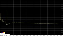
The 2nd att. shows the spectrum at the output of the LP filter mentioned earlier, using LME49710. The filter added some 8dB to the noise floor, the 2nd oscillator harmonic is now below the noise floor, and the 3rd is attenuated by more than 20dB, as the filter calculation predicted. So the 3rd is now well below -150dBc.
The 3rd att. shows the spectrum with the G&P composite op-amp in the filter. The noise floor is now higher by another 6dB, and the 3rd harmonic is barely visible.
I checked the performance of the filter theoretically and with LtSpice, and found the Bonello's THD penalty of about 13dB. Apparently, both 49710 and the G&P composite op-amp can accommodate this THD increase.
So it seems that a properly tweaked, cheap SVO filter augmented by an LP filter can offer respectable performance.
Regards,
Braca
The details of the setup are here:
Low-distortion Audio-range Oscillator
so I'm only presenting the changes.
First I tweaked the oscillator to the performance I once had - compared to the starting position from the above link, the 3rd is now almost 30dB lower, in absolute terms at about -132dBc (osc. output level of 2.5Vrms, or -6dBFS for my sound card), the 2nd is lower by 15dB, or -148dBc (first attachment).
The notch depth was about -90dBc in all measurements, and this time I used Samuel's LNA from Lin. Audio Vol. 3.
The 2nd att. shows the spectrum at the output of the LP filter mentioned earlier, using LME49710. The filter added some 8dB to the noise floor, the 2nd oscillator harmonic is now below the noise floor, and the 3rd is attenuated by more than 20dB, as the filter calculation predicted. So the 3rd is now well below -150dBc.
The 3rd att. shows the spectrum with the G&P composite op-amp in the filter. The noise floor is now higher by another 6dB, and the 3rd harmonic is barely visible.
I checked the performance of the filter theoretically and with LtSpice, and found the Bonello's THD penalty of about 13dB. Apparently, both 49710 and the G&P composite op-amp can accommodate this THD increase.
So it seems that a properly tweaked, cheap SVO filter augmented by an LP filter can offer respectable performance.
Regards,
Braca
Attachments

https://www.diyaudio.com/forums/equipment-and-tools/205304-low-distortion-audio-range-oscillator-852.html#post6128729
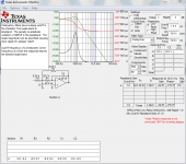
It seems to me, there is a mistake in math. 2-nd order LPF couldn't att. thd-2 by 14dB, likely 9dB for Butterworth and ~10dB with more aggressive Chebyshev. Error comes from measurement thd-2 w/o accounting att. of fundamental. In this test what is important, to keep magnitude of primary tone constant when LPF introduced in the circuits, and some gain adjustment has to be done to estimate thd-n reduction by LPF correctly.
The first spectrum shows the oscillator harmonics in the as-is version, and on the second one (LP filter in) the 2nd is lower by 14dB, and the 3rd by 17dB. Although it seems that the filter potential of 21db attenuation at the 3rd has not been fully realized, it is also the level where the THD of my audio interface comes into play.
It seems to me, there is a mistake in math. 2-nd order LPF couldn't att. thd-2 by 14dB, likely 9dB for Butterworth and ~10dB with more aggressive Chebyshev. Error comes from measurement thd-2 w/o accounting att. of fundamental. In this test what is important, to keep magnitude of primary tone constant when LPF introduced in the circuits, and some gain adjustment has to be done to estimate thd-n reduction by LPF correctly.
Thank you for analyzing and commenting my results.
A Chebyshev MFB filter with 3dB ripple in the passband can attenuate the 2nd by almost 14dB, the 3rd by at least 22dB.
The signal level at the oscillator output changes by less than 10mV when switching from the LP to the notch filter (rechecked in the current setup).
A Chebyshev MFB filter with 3dB ripple in the passband can attenuate the 2nd by almost 14dB, the 3rd by at least 22dB.
The signal level at the oscillator output changes by less than 10mV when switching from the LP to the notch filter (rechecked in the current setup).
Probably, you are right, at least AD & TI design tools agree on 14.
I want to breadboard your circuits, mind to publish?
I want to breadboard your circuits, mind to publish?
The topology using a cap in the fb is ---

FilterPro 3.0 Download (Free) - AppStart.exe
http://www.ti.com/lit/an/slyt113/slyt113.pdf
3rd order Multiple feedback Low-pass Filter Design Tool
http://www.ti.com/lit/an/sbfa001c/sbfa001c.pdf
THx-RNMarsh
FilterPro 3.0 Download (Free) - AppStart.exe
http://www.ti.com/lit/an/slyt113/slyt113.pdf
3rd order Multiple feedback Low-pass Filter Design Tool
http://www.ti.com/lit/an/sbfa001c/sbfa001c.pdf
THx-RNMarsh
Last edited:
My pleasure.Probably, you are right, at least AD & TI design tools agree on 14.
I want to breadboard your circuits, mind to publish?
The filter design is in the attachment. I used NOS polystyrene capacitors.
Re. the rest of the setup, let me know if you need anything and I'll provide the links.
Regards,
Braca
Attachments
Should be a way to auto-zero-null-subtract and not have to manually tune for a minimum.
Motorized pots? It would add enormous complexity to save what? It's not like one needs a production line instrument.
- Home
- Design & Build
- Equipment & Tools
- Low-distortion Audio-range Oscillator