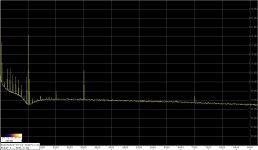
Spectra comparing LME49710 and the G&P composite op-amp in the LP filter: practically the same results in terms of the harmonics, the 49710 has a somewhat lower noise floor. The 7kHz spur in the latter spectrum is an interference I'm sometimes getting with this setup, it wasn't present in the unfiltered spectrum.
It appears that in the case of a low-order filter (2nd order in this case), a premium op-amp would be sufficient.
Regards,
Braca
It appears that in the case of a low-order filter (2nd order in this case), a premium op-amp would be sufficient.
Regards,
Braca
Attachments

I dunno, if you measure the same with such very different opamps, I'd be skeptic.
How much do I need to correct these numbers with, 60dB?
Jan
How much do I need to correct these numbers with, 60dB?
Jan
Attenuating the 3rd by 60dB is a tall order - a quick calculation with the TI's FilterPro software returns a 5th order MFB filter with three op-amps.
Attenuating the 3rd by 60dB is a tall order - a quick calculation with the TI's FilterPro software returns a 5th order MFB filter with three op-amps.
No, I mean the graph shows 90 or 100dB, what's the correction from the notch?
Jan
The notch is standard, -10dB at the 2nd, -6dB at the 3rd.
Since I've only exchanged the op-amps, and before each reading adjusted the notch for the best possible attenuation of the fundamental, the comparison of the op-amps is direct.
Passing the output of the Victor's oscillator through the filter, I only get the noise floor of the entire system. The latter is now higher by some 10dB than in the case of 4970 in the filter, which can be explained by the difference between the output impedances between the Victor's and my SVO (600 vs. 100 Ohm).
Regards,
Braca
Attachments
The noise floor of my measurement system is actually lower.
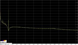
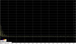
Starting with the LNA only (terminated with a 50 Ohm resistor at the input) attached to the sound card, the noise floor is about -137dB@5kHz (acq. rate 48kHz, Flat top window), s. first plot.
With the notch filter ahead of the LNA, also terminated with a 50 Ohm resistor at the input, the noise floor is -122db@5kHz (second plot). The reason for the 15dB jump is the impedance of the notch filter with its series resistance of 120 kOhm. I'm preparing a new one, which will reduce the noise floor by some 7dB, and thus bring it in line with the Twin-T filters shown in this thread.
Anything above -122dB is a contribution of the DUT's.
Regards,
Braca
Attachments

Jan Didden pointed me to this thread to clarify the measurement method used for the Low-Distortion, Low-Noise Composite Operational Amplifier paper.
With 60 dB noise gain, measuring -180 dB harmonic distortion asks for -120 dB residual from the analyzer. The SYS-2722 is 10-20 dB better than this, so no passive filters needed for that.
Samuel
This uses the active, auto-tuning notch filter of the Audio Precision SYS-2722. I think this is a 4th-order filter, see patent US4563652A or the Audio Precision System-One service manual (available for download from their website for registered users).I mean the noise floor does not show the tails of the notch where usually you have to correct for 2nd and 3rd levels. The noise floor is flat almost immediately before and after 1kHz.
With 60 dB noise gain, measuring -180 dB harmonic distortion asks for -120 dB residual from the analyzer. The SYS-2722 is 10-20 dB better than this, so no passive filters needed for that.
Samuel
With 60 dB noise gain, measuring -180 dB harmonic distortion asks for -120 dB residual from the analyzer. The SYS-2722 is 10-20 dB better than this, so no passive filters needed for that.
Samuel
Thanks for clarifying, do you think the composite op-amp used in the Q enhanced twin-tee would perform well? I forgot the 60dB noise gain changes everything, there is no "perfect" notch at those levels.
hmmmm so, it was active notch but with 60db amp and the AP2722 instead.
I have a 2722 also but didnt go low enough for the amp I was testiing. The ShibaSoku 725D is useful/accurate to -160. About 15db better than AP2722. So. What if I make a 60db amp then?
Nice thought. Something to work on while in lock-down here.
THx-RNMarsh
I have a 2722 also but didnt go low enough for the amp I was testiing. The ShibaSoku 725D is useful/accurate to -160. About 15db better than AP2722. So. What if I make a 60db amp then?
Nice thought. Something to work on while in lock-down here.
THx-RNMarsh
Jan Didden pointed me to this thread to clarify the measurement method used for the Low-Distortion, Low-Noise Composite Operational Amplifier paper.
This uses the active, auto-tuning notch filter of the Audio Precision SYS-2722. I think this is a 4th-order filter, see patent US4563652A or the Audio Precision System-One service manual (available for download from their website for registered users).
With 60 dB noise gain, measuring -180 dB harmonic distortion asks for -120 dB residual from the analyzer. The SYS-2722 is 10-20 dB better than this, so no passive filters needed for that.
Samuel
I'm confused. Are two different measurement techniques being conflated in this discussion?
If I understand correctly, Groner is testing distortion in his composite amplifier by testing with closed-loop gain of 60dB applied to his amplifer, allowing him to characterize distortion directly without resorting to outboard notch filters and subsequent post amplifier. He then uses measured results and extrapolates by 60dB.
In contrast, most of the nearby discussion seems to deal with using using a notch filter and post gain to measure low-distortion sources. Unless I'm completely lost, these are quite different beasts with equally different challenges? If the only implication is 60dB post-notch gain might be more appropriate than only 40dB, that seems reasonable.
Thanks.
Last edited:
I think there may be some confusion around noise gain. In effect the amp's voltage gain is unity but the feedback is arranged that 60 dB of open loop gain is discarded to boost the actual distortion enough to measure it. Unfortunately finding an online reference doesn't seem to be easy. There should be a test circuit for some of the premium opamps that illustrates this.
edit: section 8.3 of this illustrates the technique: http://www.ti.com/lit/ds/symlink/opa1611.pdf
Its difficult to do for a complete power amp/preamp however and can bring lots of confounders that would reduce its relevance. Still its probably the only way to test things like SG's compound amp.
edit: section 8.3 of this illustrates the technique: http://www.ti.com/lit/ds/symlink/opa1611.pdf
Its difficult to do for a complete power amp/preamp however and can bring lots of confounders that would reduce its relevance. Still its probably the only way to test things like SG's compound amp.
I think there may be some confusion around noise gain. In effect the amp's voltage gain is unity but the feedback is arranged that 60 dB of open loop gain is discarded to boost the actual distortion enough to measure it. Unfortunately finding an online reference doesn't seem to be easy. There should be a test circuit for some of the premium opamps that illustrates this.
edit: section 8.3 of this illustrates the technique: http://www.ti.com/lit/ds/symlink/opa1611.pdf
Its difficult to do for a complete power amp/preamp however and can bring lots of confounders that would reduce its relevance. Still its probably the only way to test things like SG's compound amp.
from SG's AES paper-
Measured input-referred harmonic distortion voltage at
10 kHz for the OPA211, THS4031, and resulting composite operational
amplifier.
-RNM
Some test methods also here;
https://linearaudio.nl/sites/linearaudio.net/files/Xavier ultra low distortion article_0.pdf
Last edited:
Its difficult to do for a complete power amp/preamp however and can bring lots of confounders that would reduce its relevance. Still its probably the only way to test things like SG's compound amp.
Bob Pease also had this app on National's data sheets a while ago as well as Bob Cordell's distortion magnifier. I even published it in 1992 as an instrumentation amplifier application. It does need attention to the phase response of the amplifier but this is not insurmountable, and with PA's there are the usual problems of dealing with very high signal levels.
This is all beside the point, this is no help in measuring the output of an oscillator.
Slight change of subject...
Has anyone tried using voltage controlled capacitance in a SVF?
I don't know of any that are linear enough.
Thanks, Demian. This is exactly the technique I was recalling but I didn't allude to it very coherently and certainly didn't distinguish between closed-loop gain and noise gain in my post.
I was thinking further about desirable characteristics of a post-Twin-T notch filter. It appears to me that it should be non-inverting so that it imposes negligible loading of the Twin-T; it should have good noise figure since the filter that drives it is lossy and will degrade sensitivity to distortion and noise artifacts; it should have gain that delivers noise density that is about 10 to 15dB above the noise floor of the sound card so that observed noise is dominated by noise emerging from the Twin-T. Gain that is needlessly larger might risk overload from imperfect suppression of the fundamental.
I was thinking further about desirable characteristics of a post-Twin-T notch filter. It appears to me that it should be non-inverting so that it imposes negligible loading of the Twin-T; it should have good noise figure since the filter that drives it is lossy and will degrade sensitivity to distortion and noise artifacts; it should have gain that delivers noise density that is about 10 to 15dB above the noise floor of the sound card so that observed noise is dominated by noise emerging from the Twin-T. Gain that is needlessly larger might risk overload from imperfect suppression of the fundamental.
Slight change of subject...
Has anyone tried using voltage controlled capacitance in a SVF?
I have not tried it, but I don't think it would work well in terms of distortion. This is due to the very nature of Varicaps, as we used to call them. These are actually diodes whose doping profile and design are intentionally made to cause its capacitance to be quite sensitive to voltage. For this reason, the signal across them, unless very small, will cause the capacitance to change with instantaneous signal voltage, thus causing distortion. Indeed, most diodes exhibit Varicap behavior to some extent. For example, the collector-base capacitance in an ordinary VAS transistor can cause distortion, especially in a one-transistor VAS.
Varicap distortion can be mitigated a bit by putting two of them back-to-back and applying the control voltage at their junction. This tends to suppress the 2nd harmonic component of their distortion.
Cheers,
Bob
I think there may be some confusion around noise gain. In effect the amp's voltage gain is unity but the feedback is arranged that 60 dB of open loop gain is discarded to boost the actual distortion enough to measure it. Unfortunately finding an online reference doesn't seem to be easy. There should be a test circuit for some of the premium opamps that illustrates this.
edit: section 8.3 of this illustrates the technique: http://www.ti.com/lit/ds/symlink/opa1611.pdf
Its difficult to do for a complete power amp/preamp however and can bring lots of confounders that would reduce its relevance. Still its probably the only way to test things like SG's compound amp.
This is the method I used to measure my Groner/Polak opamps.
Jan
I see no reason why it shouldn't work well. With a properly tuned notch filter the amplifier input and output voltage and thus the basic amplifier transfer nonlinearity will be very low anyway even for a standard opamp. But the composite opamp will help to reduce any potential distortion generated from signal current flowing into the amplifier output through the bootstrapping node.Do you think the composite op-amp used in the Q enhanced twin-tee would perform well?
Correct.I think there may be some confusion around noise gain. In effect the amp's voltage gain is unity but the feedback is arranged that 60 dB of open loop gain is discarded to boost the actual distortion enough to measure it.
I probably learned the technique from Walt Jung's opamp measurement series. It's also used for my opamp measurement series (opamp_distortion.pdf, page 8).Unfortunately finding an online reference doesn't seem to be easy.
A related approach is to configure the opamp in a standard inverting configuration, and look at the error voltage across the inputs. This is a very low signal, so it will need a low-noise preamplification. In the discussed approach with high noise gain, the opamp itself provides the amplification. However, looking directly at the error voltage is possible in all sorts of inverting configurations, for example also within a state-variable oscillator under full operation.Still its probably the only way to test things like SG's compound amp.
Samuel
- Home
- Design & Build
- Equipment & Tools
- Low-distortion Audio-range Oscillator