The FET distortion problem was discussed some time ago, and the radical method is the balanced FET regulator. As example in the attachment. Other simple method may be paralleling or cascoding of the FETs, if we can't find the FET with needed specification. As example, the MMBF4391 runs in my oscillator with around 40 ohms resistance. The fully open resistance of this FET is around 20 ohms. So, I have only 20 ohms for to change, but other 20 ohms as unwanted ballast. When I use the matched FET in parallel, I can reduce the resistance and also the voltage across the FETs without losing the same control.
Also other serious problems we can find under -150dB - capacitors, opamps and the PCB board quality. Some PCB boards don't allow to run so low. Maybe chemical residues, moisture, bad mask or PCB material. The oscillator under -160dB probably must be mounted on teflon board without the mask, or air mounted - point to point soldered.
Vic.
Hi Victor,
That JFET regulator is a neat-looking circuit. Did you come up with it, or did it originate with someone else? Have you simulated it? If it works as my initial look suggests, both for H2 and H3, it seems that it should ideally cancel distortions without the 50% gate feedback trick. Is that right? I'm not saying to abandon the 50% feedback trick (invented by HP when they first started using JFETs for agc control in their oscillators), but rather am suggesting that seeing how well this circuit works without that gate feedback is a good sanity check on its effectiveness.
Cheers,
Bob
Hi Bob,Hi Victor,
That JFET regulator is a neat-looking circuit. Did you come up with it, or did it originate with someone else? Have you simulated it? If it works as my initial look suggests, both for H2 and H3, it seems that it should ideally cancel distortions without the 50% gate feedback trick. Is that right? I'm not saying to abandon the 50% feedback trick (invented by HP when they first started using JFETs for agc control in their oscillators), but rather am suggesting that seeing how well this circuit works without that gate feedback is a good sanity check on its effectiveness.
Cheers,
Bob
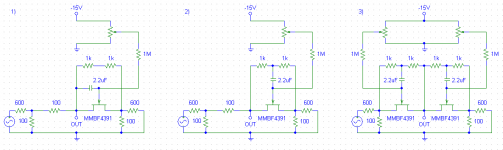
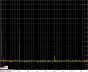
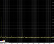
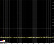
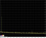
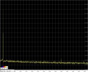
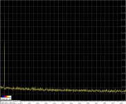
This balanced regulator was drawn by me, but idea is very old and was implemented in some devices, and in other configuration. In theory it can run without the 50% feedback, but then it needs very precisely matched FETs. I haven't try this schematic yet, but I was tried the compensation principle in simplified schematic (schematic 3 in first attachment) with two FETs connected as divider. I measured it, and the results was published when the previous discussion was going on. The principle works fine, and also without the very precisely matched FETs. You can see the spectrum comparisons between the schematics in the same sequence as drawn schematics.
Vic.
Attachments
Last edited:
My admiration to all of your for advancing the art.
Yet another crucial aspect of the oscillator is the performance of the amplitude detector. I think this is widely appreciated, but I want to make a mild harangue on the issue.
As a thought experiment, let’s presume components with perfect linearity--- opamps, passives, and a FET that is an ideal voltage controlled resistor. VCR? ;-) With an appropriate manipulation of the gate voltage on the FET, we’d be able to start and maintain a distortion free sine wave.
But the ideal VCR is equivalently an ideal multiplier, aka a modulator, aka a (frequency) mixer. If we assume a small sine wave at the fundamental frequency appears as ripple on the FET gate, frequency mixing generates 2nd harmonic energy and our perfectly linear circuit delivers 2nd harmonic distortion.
Obviously, control ripple has to be suppressed until it has negligible contribution to overall distortion. A good sample/hold could be useful element in the control loop. Also well known, I believe.
Best,
Steve
As a thought experiment, let’s presume components with perfect linearity--- opamps, passives, and a FET that is an ideal voltage controlled resistor. VCR? ;-) With an appropriate manipulation of the gate voltage on the FET, we’d be able to start and maintain a distortion free sine wave.
As B. Oliver showed a long time ago, you can't make a truly distortion-less oscillator, the time constant on the amplitude stability goes to infinity as distortion goes to zero.
Hi Bob,
This balanced regulator was drawn by me, but idea is very old and was implemented in some devices, and in other configuration. In theory it can run without the 50% feedback, but then it needs very precisely matched FETs. I haven't try this schematic yet, but I was tried the compensation principle in simplified schematic (schematic 3 in first attachment) with two FETs connected as divider. I measured it, and the results was published when the previous discussion was going on. The principle works fine, and also without the very precisely matched FETs. You can see the spectrum comparisons between the schematics in the same sequence as drawn schematics.
Vic.
Nice work, Victor. I used the 2N4091 back in 1981 when I did my distortion analyzer, and as far as I can tell the 2N4391 is pretty much the same. I picked the 2N4091 because it had high pinchoff voltage and low Rds-on.
The 50% gate feedback does need to be quite precise for best distortion reduction, especially for the 2H. I have seen evidence that it is not always exactly 50% at the optimum, and have 10-turn pots in my distortion analyzer for adjusting that ratio. In the arrangement I use, the JFET and an associated op amp implements essentially a 4 quadrant multiplier that creates an error signal that is injected into the SVF for control. I can thus see quite easily the in-situ distortion created by the JFET circuit on a spectrum analyzer. That makes it easy to adjust the pot for the optimum.
The other thing that I discovered is that the phase of the 50% gate feedback signal is very important, and any (usually lagging) phase shift of that signal can seriously limit the degree to which the technique can reduce the distortion. This phenomena often does not show up at 1 kHz, but does tend to be something that needs to be considered when measuring a 20 kHz fundamental.
Cheers,
Bob
My admiration to all of your for advancing the art.
Yet another crucial aspect of the oscillator is the performance of the amplitude detector. I think this is widely appreciated, but I want to make a mild harangue on the issue.
As a thought experiment, let’s presume components with perfect linearity--- opamps, passives, and a FET that is an ideal voltage controlled resistor. VCR? ;-) With an appropriate manipulation of the gate voltage on the FET, we’d be able to start and maintain a distortion free sine wave.
But the ideal VCR is equivalently an ideal multiplier, aka a modulator, aka a (frequency) mixer. If we assume a small sine wave at the fundamental frequency appears as ripple on the FET gate, frequency mixing generates 2nd harmonic energy and our perfectly linear circuit delivers 2nd harmonic distortion.
Obviously, control ripple has to be suppressed until it has negligible contribution to overall distortion. A good sample/hold could be useful element in the control loop. Also well known, I believe.
Best,
Steve
These are good points, and it is always important in any oscillator design to know which is the largest contributor to the distortion: the JFET device, the amplitude detector or the op amps. There are ways that one can make changes in the circuit by experiment to see which of these is the biggest contributor. Your modulator analogy is a good one, but in most decent oscillators the amplitude detector will be full-wave, so the modulating signal will be second harmonic, not fundamental.
The sample-hold in theory often seems to be the be-all to end all, but in practice it often doesn't work as well as one would hope at high frequencies.
In a state variable oscillator, the quadrature phases are conveniently available, and you can make a 4-phase detector that has quite low ripple and at twice the frequency. While the valley in a full-wave signal goes all the way to zero, the valley in a 4-phase rectified signal theoretically never goes below 0.707 of the peak.
If you really wanted to go crazy, you could make an 8-phase detector by combining in-phase and quadrature signals to get a peak every 45 degrees.
Cheers,
Bob
Thank you, Bob.Nice work, Victor. I used the 2N4091 back in 1981 when I did my distortion analyzer, and as far as I can tell the 2N4391 is pretty much the same. I picked the 2N4091 because it had high pinchoff voltage and low Rds-on.
The 50% gate feedback does need to be quite precise for best distortion reduction, especially for the 2H. I have seen evidence that it is not always exactly 50% at the optimum, and have 10-turn pots in my distortion analyzer for adjusting that ratio. In the arrangement I use, the JFET and an associated op amp implements essentially a 4 quadrant multiplier that creates an error signal that is injected into the SVF for control. I can thus see quite easily the in-situ distortion created by the JFET circuit on a spectrum analyzer. That makes it easy to adjust the pot for the optimum.
The other thing that I discovered is that the phase of the 50% gate feedback signal is very important, and any (usually lagging) phase shift of that signal can seriously limit the degree to which the technique can reduce the distortion. This phenomena often does not show up at 1 kHz, but does tend to be something that needs to be considered when measuring a 20 kHz fundamental.
Cheers,
Bob
Yes, I know about the FET feedback tuning trick, and I tried it. I think this also may eliminates the 2nd which comes from the other parts of the oscillator and the measurement tool. The worst situation may be if the measurement tool has the similar 2nd in opposite phase, and we get the wrong result.
Vic.
There is also the option of adding a cancellation term. Amber does this in the 3501 deriving the harmonics from the level rectifier and adding a small amount to null harmonics.
I have an old ACV calibrator with very low distortion for the time (.005% early 1970's) that uses a state variable oscillator and sample and hold for amplitude stability, obviously very important for a voltage calibrator. It dispenses with the sample and hold for the 100 KHz to 1 MHz band. it also has pretty complex circuitry being pre IC design.
I can supply schematics on request if interested.
Thanks for your comments, Bob. I was trying to make the point that control ripple unavoidably generates distortion. Of course, 2H distortion in the ripple could beget 3H, and it turn 4H, etc, etc.
BTW, I etched boards, built your THD analyzer and debugged on bench as you prescribed. Had all the rotary switches found at a Ham Fest. But never finished. That's been over 30 years ago. 🙁 Now I'm 71. Maybe when I retire in a few months...
Of all the neat circuitry in that instrument, I most admired your VCA. With just the FET and one opamp, it applied the FET linearization, and performed 4-quadrant multiplication; voltage impressed across the FET was held constant irrespective of gate voltage. Clever.
Best regards,
Steve
My oscillator boards concept was to get best as possible performance/cost ratio and the main target was sine purity for linearity tests.
The OPA627 is very good for sonic - I accept, but the open loop gain and the output impedance is not so good as the LM4562/LME49720 has. These LM opamps are the best what I ever tried for my oscillators.
According my experience, FKP2s overall are better and more stable in performance than COGs. COGs need to be selected for low distortions - the performance has visible variations from part to part.
Metal film resistors are good enough for to get harmonics -160dB and lower.
Vic.
I have seen that Analog Precision substituted a polyprop capacitor for several NP0s connected in parallel and had even less distortion. The NP0 types can not be that bad. Maybe they are still selected.
What type of polypropylenes AP used before? Metalized film or film/foil? What distortion figures AP has with the new ones?I have seen that Analog Precision substituted a polyprop capacitor for several NP0s connected in parallel and had even less distortion. The NP0 types can not be that bad. Maybe they are still selected.
Vic.
It should be possible to select resistors for the tuning network with a matching complementary temperature coefficient for frequency stability. Polyproplene seems to have around -200 PPM tempco. So a resistor selected for the same tempco could balance it to keep the same time constants and frequency as its ambient changes. I know this can work quite well. it was used in the 1960's and 1970's for stable RC oscillators, that still are stable enough.
Just one question: how the 200ppm resistors distort?It should be possible to select resistors for the tuning network with a matching complementary temperature coefficient for frequency stability. Polyproplene seems to have around -200 PPM tempco. So a resistor selected for the same tempco could balance it to keep the same time constants and frequency as its ambient changes. I know this can work quite well. it was used in the 1960's and 1970's for stable RC oscillators, that still are stable enough.
Very valid question. In the past .001% was the state of the art. We are approaching 40 dB better today. For the truly obsessive you would have custom wirewound resistors made that don't distort, but we all live in the real world. I'll poke around to see what is available today. Maybe get some samples and test them on the CLT-1 (????? ?????????). It should give some clues.
The temperature compensating resistors seem to be obsolete. Looking, it seems you can now get Polysulfone (e.g. http://datasheets.avx.com/cb-pps.pdf) caps in SMT. Polypropylene and polystyrene (best choice) are not available in surface mount but are in through hole. Polystyrene and Polysulfone are about .5% change from 20c to 60c so good for stability. More research needed. Teflon is great but goes with the custom wirewound resistors as not practical.
What type of polypropylenes AP used before? Metalized film or film/foil? What distortion figures AP has with the new ones?
Vic.
YouTube 42:15
YouTube 42:15
The PP capacitor types what they tested are unknown. Also the 15Hz frequency is very low. I trust for the COG figures, but I never saw so high figures for Wima FKP2 at 1kHz 2,7V RMS. They run not higher than -155dB in my conditions.
Vic.
Are the Wima FKP better than the Wima MKP??? You compare SMDs to thru hole here. I think the thru holes are unbeatable because they are bigger and mechanically better. The manufacturer does not have the space problems here. The FKP2 measurements are really world class.
- Home
- Design & Build
- Equipment & Tools
- Low-distortion Audio-range Oscillator