Yes, but I don't want to damage the PCB. Just disable them, like Vic said, that will also leave in place the 1000uF caps on each polarity.
Jan
Jan
Hi Victor,
I currently compare various measurement software (Arta, AudioTester, REW, SpectraPlus, WaveForms). Your Low-distortion Audio-range Oscillator serves as a kind of reference.
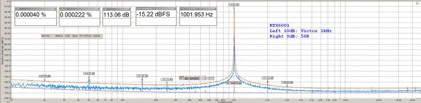
Would like to share Arta and SpectraPlus curves with FFT 131072 vs 1048576.
BTW:
I didn't observe significant differences between 4x 9V batteries and an >30 years old Voltcraft lab psu feeding the Low-distortion Audio-range Oscillator.
Best
Ulli
I currently compare various measurement software (Arta, AudioTester, REW, SpectraPlus, WaveForms). Your Low-distortion Audio-range Oscillator serves as a kind of reference.
Would like to share Arta and SpectraPlus curves with FFT 131072 vs 1048576.
BTW:
I didn't observe significant differences between 4x 9V batteries and an >30 years old Voltcraft lab psu feeding the Low-distortion Audio-range Oscillator.
Best
Ulli
Attachments
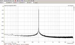
If you are pursuing supply noise related issue or checking ultra low distortion analyzers the power line noise can be an issue. The -140 dB spur at 50 Hz is an example that should be completely ignorable except for the above cases. I have 3 oscillators from the first gen and they all work fine. I'm running them from a battery and constant current source to get more life from the 4 9V cells (they get expensive fast). The only issue I have noted is a steady downward drift in frequency. The 997 Hz oscillator is now 994 Hz. The noise floor is limited by the 600 Ohm source resistor. The internal noise is lower. and the PSRR of the opamps is enough that the '431s are not a real issue. I don't think you can just bypass them easily. You could disable them by shorting the sense terminal to ground. One of the great tricks is the floating supply which reduces the potential supply noise getting into the circuitry. The oscillators should run fine from a single 35V floating output switcher. Not that this is a great solution but this is available for $0.75 XL6009 *1Pcs DC-DC Adjustable Step-up Power Converter Module Bette r than LM2577 | eBay and I may switch so I can use rechargable LI batteries. Unfortunately its not isolated so no easy implementation. . .
Thank you Vic,
When I have access to to oscillator I come back with the answers, but it's THD and a QA400.
Miklos
When I have access to to oscillator I come back with the answers, but it's THD and a QA400.
Miklos
You could disable them by shorting the sense terminal to ground.
Yes I did and connected up a SilentSwitcher, running from a Powerbank. Seems to run fine, although some amplitude bounce but it had that before. Measuring tomorrow.
Jan
Yes.Ulli is this with Jens' RTX?
With one additional mod: wires to mains switch are not in use => less 50 Hz peaks.
Ulli
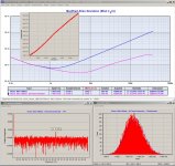
I noticed that the Low-distortion Audio-range Oscillator frequency is a bit unstable: in SpectraPlus the marker can be set manually - they have to be aligned after about 15-30 min.
Measurement done with 53230A confirms that observation (see attached image).
Ulli
Measurement done with 53230A confirms that observation (see attached image).
- TimeLab used to collect data
- collected data do have a linear trend (blue curve)
- trend removed gives the remaining instabilty (purple curve)
. - Plotter used for further investigation
- sample distribution is quite good - more or less just gaussian noise
- FFT does show a peak @ 28 Hz - no idea what it comes from.
Ulli
Attachments
Last edited:
RC oscillators can be quite stable, even tuneable ones, but a lot of care is needed to use stable parts, preferably ones that have aged some and to match and balance the thermal properties so they can cancel. I have seen the startup shift as well but on mine the frequency increases, starting at 991 Hz and slowly increasing to 994 Hz. I think it thermal aspects of the R/C that sets the frequency. It has not been a big issue but it is an issue for large FFT's since the harmonics change during the measurements and sometimes just go away as it drifts from bin to bin.
No clue yet how stable such type of oscillator can be made...
Ulli
Hi Ulli,
Nice measurements.
Of course the RC oscillator is sensitive to the temperature drifts. The Wima FKP2 capacitors have 200ppm/C. If the highest frequency stability is needed from this oscillator, then the board must be placed in a closed box, needs to wait app. 20 min. after start up for warm up and the room temperature also must be stable without the non stable air flux.
Regarding the short term frequency drifts. The oscillator runs on the "thin line". Every noise variations can affect. Practically all the LME49720/LM4562 opamps have the small "popcorn" noise components. Also the AGC system has different reaction depending of the adjusted output level, because the adjustment runs via AGC for to get lower distortions. The AGC is more stable in higher output level positions and becomes more inertial and unstable when the output is low. Mechanical vibrations also can affect the board and an the EMI of course.
Hi Victor,

Could imagine an improved version...
Ulli
thanksNice measurements.
Could imagine an improved version...
- LM4562
long story short: out of several opamp in sonic evaluation the OPA627 was the one we choose
- yes, it's single and it is a bit expensive...
Samuel Groners work might help to choose one... - FKP2
what about C0G/NP0 ?... - Resistor
what about foil resistors ?... - OCXO concept
some box internal heating might help
- some stable 40-50 °C inside the box should be feasibe...
Ulli
Last edited:
Does anyone here have experience with distortion caused by (feedback) resistors? I am slowly finding out that at -120dB, EVERYTHING matters ...😱
Jan
Jan
Ulli,
I should let Viktor answer, but AFAIK they have all been considered / tried before.
And you probably will not pay 100x the price for bulk foils and oven control, ....., etc.
Not that bulk foils are necessarily better in measurable distortion, as Jan will tell you.
Cheers,
Patrick
I should let Viktor answer, but AFAIK they have all been considered / tried before.
And you probably will not pay 100x the price for bulk foils and oven control, ....., etc.
Not that bulk foils are necessarily better in measurable distortion, as Jan will tell you.
Cheers,
Patrick
Does anyone here have experience with distortion caused by (feedback) resistors? I am slowly finding out that at -120dB, EVERYTHING matters ...😱
Jan
Jan just reduce the voltage across the resistor(s). Use series resistors rather than one and 1/2 watt if you have the space.
A member involved in AP design mentioned with small surface mount that if he just touched the resistor with his finger the distortion would drop. Size matters.
There is info from both Sam Groner and Bruce Hofer : From the Test Bench: Resistor noise and non-linearity - Audio Precision I have 2 Radiometer CLT-1's for looking at component distortion. Unfortunately they only work at 10 KHz but they do have a floor at close to -170 dB.
First trick, use a much larger power resistor. Second, use metal film. Third, it seems the MELF style is the best of the surface mount options. Metal foil resistors are great until you get to the low frequency areas where the internal thermal time constants show up.
First trick, use a much larger power resistor. Second, use metal film. Third, it seems the MELF style is the best of the surface mount options. Metal foil resistors are great until you get to the low frequency areas where the internal thermal time constants show up.
Last edited:
Hi Victor,
thanks
Could imagine an improved version...
Any comments?
- LM4562
long story short: out of several opamp in sonic evaluation the OPA627 was the one we choose
- yes, it's single and it is a bit expensive...
Samuel Groners work might help to choose one...- FKP2
what about C0G/NP0 ?...- Resistor
what about foil resistors ?...- OCXO concept
some box internal heating might help
- some stable 40-50 °C inside the box should be feasibe...
Ulli
Unfortunately sonic eval doesn't show correlation to low distortion. The best opamp would most probably have low distortion and high gain bandwidth product. The best candidates would be the discontinued LME49990, the OPA1611/OPA1612, the AD797 and the LT1115. However when you already have lower distortion than any analyzer there is not much to gain.
Switching to polystyrene caps (not really a current product) or COG ceramic could make a difference in stability. MELF resistors seem to also be a good practical choice.
Ovenizing not really practical and will impact the noise floor.
I tried injection locking to a crystal stabilized source but the distortion penalty was too high even though the source was very low distortion.
Could imagine an improved version...
Ulli
My oscillator boards concept was to get best as possible performance/cost ratio and the main target was sine purity for linearity tests.
The OPA627 is very good for sonic - I accept, but the open loop gain and the output impedance is not so good as the LM4562/LME49720 has. These LM opamps are the best what I ever tried for my oscillators.
According my experience, FKP2s overall are better and more stable in performance than COGs. COGs need to be selected for low distortions - the performance has visible variations from part to part.
Metal film resistors are good enough for to get harmonics -160dB and lower.
Vic.
Last edited:
Does anyone here have experience with distortion caused by (feedback) resistors? I am slowly finding out that at -120dB, EVERYTHING matters ...😱
Jan
There was an article in Linear Audio that covered that. Widely copied but not completely understood by some of the copiers.
Best low cost results come from Dale metal film resistors at 25PPM thermal coefficient and use the largest wattage you can fit up to about 2 watts. Works at least as well as bulk metal resistors at a much lower price.
Even better results with two of 1/2 the value in series and folded back on each other to reduce the inductance to pretty much un-measurable levels.
🙂
- Home
- Design & Build
- Equipment & Tools
- Low-distortion Audio-range Oscillator