Well I have some FR-4... a dissipation factor of .025 @ 1 Mhz...a loss tangent of .015 at 1 Mhz...
Why is the dissipation factor not equal to the loss tangent?
Best wishes
David
Why is the dissipation factor not equal to the loss tangent?
Best wishes
David
Considerations for a High Performance Capacitor - by Richard Marsh
THx-RNMarsh
I think we...
I try for "sufficient for any reasonable requirement".
My main satisfaction is to use simplicity to achieve excellence.
A sort of zen aesthetic to meet specifications with an elegant solution that follows from a deep view of the problem.
If you want "excessive for unreasonable requirements" then I can see the fun but it's not my interest.
My comment that the Audio Precision System 1 is "pretty adequate" was a deliberate understatement.
But in 7 years in the USA I found few Americans who picked up on understatement or irony, so I should have learned this cultural difference by now, mea culpa.
Best wishes
David
I don't see an answer to my question.
You say dissipation factor is an equivalent term to loss tangent, just in a different context, typically at lower frequencies.
I also consider them equivalent, so how can they be different at the same frequency?
Best wishes
David
You mean U251 - the AD7523?
That looks like a frequency fine trim, a computer controlled version of the vernier on the Tek 505.
Have I missed some implications on the multiplier to oscillator gain?
You mean his composite amplifier stuff?
I know the LT "super oscillator" does this but it seems unnecessary complexity.
The Sys 1 uses 5534 op-amps and is already pretty adequate.
A replacement with AD797 should increase the return ratio (feedback) by 20 dB or more.
The 797 is not simple first order so the improvement varies with frequency but I expect that to be sufficient for any reasonable requirement.
Have I overlooked some point?
Any comment JCX?
Best wishes
David
I don't have the numbers in front of me, but check to see if the AD797 has significantly more input current noise. That could increase oscillator noise or require you to use lower-impedance tuning elements to keep the noise the same.
Also, I would not rule out the LM4562.
Cheers,
Bob
I don't have the numbers in front of me, but check... input current noise. That could increase oscillator noise or require you to use lower-impedance...
I did the numbers back >HERE<
I can't find a lower combination of potential and current noise at an impedance the op-amp can drive.
The LME 49990 has worse current noise.
The LT1115 and LT1128/LT1028 are theoretically a bit quieter but Samuel's test show they don't cleanly drive the required low impedance.
The OPA1611 looks close but I don't have reliable data from Samuel to confirm this.
Also, I would not rule out the LM4562.
The fractionally lower current noise of the LM4562 would not seem to make up for the substantially worse potential noise, at recommended impedance levels.
I know there are issues with input bias current cancellation and the consequences of unbalanced input impedances, but the AD797 still looks the best AFAIK.
Best wishes
David
Why is the dissipation factor not equal to the loss tangent?
Best wishes
David
Those were the numbers on the package. I suspect what got lost in the translation were the words minimum, maximum or typical.
I don't see an answer to my question.
You say dissipation factor is an equivalent term to loss tangent, just in a different context, typically at lower frequencies.
I also consider them equivalent, so how can they be different at the same frequency?
Best wishes
David
The ESR is composed of two parts in series. Low freq part is bulk metal, termination, and low freq dielectric losses. At HF, the losses are additive to the low freq losses. The tan losses are all from the dielectric. The total is a quasi-exponential curve increasing with freq. It is more easily measured by looking at the volt-current angle change with freq. away from 90 degrees.
Does that help you?
THx-RNMarsh
I did the numbers back >HERE<
I can't find a lower combination of potential and current noise at an impedance the op-amp can drive.
The LME 49990 has worse current noise.
The LT1115 and LT1128/LT1028 are theoretically a bit quieter but Samuel's test show they don't cleanly drive the required low impedance.
The OPA1611 looks close but I don't have reliable data from Samuel to confirm this.
The fractionally lower current noise of the LM4562 would not seem to make up for the substantially worse potential noise, at recommended impedance levels.
I know there are issues with input bias current cancellation and the consequences of unbalanced input impedances, but the AD797 still looks the best AFAIK.
Best wishes
David
Hi David,
I think we are out of sync in our understanding. You pointed out that the noise impedance of the AD797 is about 600 ohms (en/in), the source impedance for which total noise contribution is minimum. However, the noise impedance does not want to be this low for the integrator op amps in the SVO, otherwise rather large capacitors and small resistances would be needed for the tuning elements. I'm guessing that the op amp wants to have a noise impedance on the order of the tuning resistance into the integrator at the geometric mean frequency of the band, as a compromise.
An op amp with higher noise impedance does not necessarily have higher noise in a given impedance environment. I think that what counts is what I'll call the noise figure of merit, that would likely be the product of en and in, or the square root of that product.
In general, I think you design the impedance of the tuning elements as low as you are willing to go, then go find an ultra low distortion op amp that has the closest noise impedance and the best noise figure of merit. I don't consider myself to be a noise guru, but this is what I'm guessing.
This line of reasoning might also suggest that wein bridge oscillators that are tuned with variable air capacitors might be a bit noisy at low frequencies if they used a bipolar op amp. Indeed, with the high impedances involved at low frequencies in these designs, they might also be a bit noisy with FET op amps.
Cheers,
Bob
If the impedance is in the "few kohm range" the OPA209 could be a good choice, with an en/in of 4400ohm (en = 2.2nV/rtHz and in = 0.5pA/rtHz). Or the OPA2209 if you want a dual.
What is the target for the impedance, if there is one?
What is the target for the impedance, if there is one?
I think we are out of sync... You pointed out that the noise impedance of the AD797 is about 600 ohms (en/in), the source impedance for which total noise contribution is minimum. However, the noise impedance does not want to be this low...
I think we understand this similarly, mainly a difference in how far to push.
I actually calculate the noise impedance of the AD797 is about 450 ohms.
This is the impedance with lowest noise power but perhaps too much load for low distortion.
But I don't see why 600 is too low, the amp will drive it well.
There's no problem with lower value resistors, so the only issue is increased capacitor values.
I think people have been conservative and stuck with typical "prior art" values, but capacitor tech has improved.
Multi Layer Ceramic Capacitors in NP0 are now available up to 1uF.
So I can use excellent NP0 and still keep the impedance down to 600 or 1k ohms.
Maybe a 10 uF film/foil for the lowest decade, finally, a sensible use for those "audiophile" capacitors😉
Anyone know an affordable 10 uF film/foil?
..the OPA209..with an en/in of 4400ohm (en = 2.2nV/rtHz and in = 0.5pA/rtHz).
A bit too much but thanks.
Any updates on the audio analyser?
Best wishes
David
Last edited:
If the impedance is in the "few kohm range" the OPA209 could be a good choice, with an en/in of 4400ohm (en = 2.2nV/rtHz and in = 0.5pA/rtHz). Or the OPA2209 if you want a dual.
What is the target for the impedance, if there is one?
In the oscillator for my THD analyzer, the integrator resistor value is about 2.2k at the geometric middle of the frequency range, so I'm guessing that the target would be in the neighborhood of that value. I think the optimum op amp noise impedance is quite broad.
Although not stated as a particular feature, it looks like the OPA209 has quite respectably low THD on the order of -110dB at 20kHz driving 3V into 600 ohms, and on the order of -130 at 1kHz. By comparison, the LM4562 is spec'd at -126dB at 20kHz under the same conditions. Spec differences at 1kHz are about the same, but at -130dB things get pretty fuzzy. In my view, 20kHz is where the rubber meets the road.
The LM4562 is spec'd at 2.7nV/rt Hz and 1.6pA/rt Hz, so its noise impedance is lower and its "noise figure of merit" is not as good.
For reference, the NE5534 is spec'd at 3.5nV/rt Hz and 0.4pA/rt Hz.
The OPA209 would be quite competitive for this application.
Cheers,
Bob
...The LM4562 is spec'd at 2.7nV/rt Hz and 1.6pA/rt Hz, so its noise impedance is lower...
Noise power is lowest at the noise impedance but does this matter when we don't impedance match?
I don't think our application is comparable to, say, a matched RF antenna.
Instead we have an output buffer amp that sees the noise V.
So shouldn't we try for the lowest source impedance we can?
For our State Variable oscillator the source impedance of one section is the load impedance of the previous section so the lowest acceptable load impedance sets the minimum.
So I think the noise FOM is En squared + (In * minimum cleanly drivable load) squared.
I looked at the noise impedance only to find a ballpark number to try.
Have I overlooked some point?
Best wishes
David
Yes, Dave, I'm pretty sure you're looking for the lowest noise energy spectra on absolute basis, as you describe, rather than necessarily balancing the relative contributions of each respectively. As such, it's going to be toggling network impedance against opamp drive capability against overall noise energy. Which seems, to a first order, to examine minimum feedback impedance you can get parts for followed by best opamp to handle that impedance. From there, you're just playing with racheting up network impedance to meet a sweet spot with a given opamp.
Likewise, irony, especially subtle, is very hard to pick up in written form. 🙂
Likewise, irony, especially subtle, is very hard to pick up in written form. 🙂
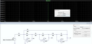
SVF noise LP out
That certainly proves Samuel's point that the resonance causes the noise to be rather concentrated😉
Probably clearer to show the noise on a dB scale.
I think that if the op-amps are to "see" a 600 load then the resistors need to increase because they are effectively in parallel with the feedback capacitors or resistor.
I also think it's time to fix my Spice computer, even if it's educational to work this stuff out, because that plot raises a few questions.
Like "what is the impact of noise very close to the tuned frequency".
Presumably that causes the noticeable "skirt" around the frequency peak on Bode plots, so would lower noise op-amps help?
For the sake of demonstration you could rerun the sim with the resistors well below the noise impedance (I think the macro models are linear and will work for a noise sim, even at unrealistic loads).
Noise should be lower.
Best wishes
David
Last edited:
.... Which seems, to a first order, to examine minimum feedback impedance you can get parts for followed by best opamp to handle that impedance...
Yes, pretty much, even if parts aren't a major constraint for an audio oscillator. 1 k ohm with 10 uF is less than 20 Hz and a film/foil unit is about $50 even at boutique "audiophile" prices, so that's tolerable.
Anyone know of an industrially priced equivalent?
Best wishes
David
Not sure if I posted this before but the nippon audio ldo module CR-tuned oscillator to 20kHz max, lists
2nd harmonic 0.00002% (-134 dB)
3rd harmonic 0.00002% (-134 dB)
thd+noise 0.00005 percent (-126 dB)
hdm_1cat.pdf
sorry about the Japanese
2nd harmonic 0.00002% (-134 dB)
3rd harmonic 0.00002% (-134 dB)
thd+noise 0.00005 percent (-126 dB)
hdm_1cat.pdf
sorry about the Japanese
Noise power is lowest at the noise impedance but does this matter when we don't impedance match?
I don't think our application is comparable to, say, a matched RF antenna.
Instead we have an output buffer amp that sees the noise V.
So shouldn't we try for the lowest source impedance we can?
For our State Variable oscillator the source impedance of one section is the load impedance of the previous section so the lowest acceptable load impedance sets the minimum.
So I think the noise FOM is En squared + (In * minimum cleanly drivable load) squared.
I looked at the noise impedance only to find a ballpark number to try.
Have I overlooked some point?
Best wishes
David
It doesn't matter if we impedance match, per se, and it is not really analogous to RF stuff. All I am saying is that once you pick the operating impedance of the integrator R and C in the SVO (whatever that value may be), the lowest total noise contribution will occur if the input noise impedance of the op amp (this is not a physical impedance) is about the same as the operating impedance of the R and C.
Moreover, if you want to use an op amp with low input noise impedance, that is fine, but you will only take maximum advantage of its low noise if you use appropriately larger values of R and C in the integrators. These are just tradeoffs. The components become larger and more expensive, and THD of the op amps may go up as a result of driving the heavier load.
The class AB output stage of an op amp can be a significant contributor to its distortion. Just because the op amp does a fine job of driving 600 ohms doesn't mean that its distortion will not be even significantly lower driving a lighter load.
Cheers,
Bob
... once you pick the ...R and C in the SVO (whatever that value may be), the lowest total noise contribution will occur if the input noise impedance of the op amp (this is not a physical impedance) is about the same as the...impedance of the R and C.
Not as I understand your comment.
Say the op-amp is 1nV/rtHz and 2 pA/rtHz for a noise impedance of 500 ohms.
If the source is indeed 500 ohms then
noise = rt(1 nV ^2 + (2 pA * 500 ohms) ^2)
= 1.41 nV /rtHz
Now keep the source impedance at 500 ohms but hypothetically reduce the current noise to 1 pA/rtHz, the noise impedance rises to 1 k ohm.
But now noise drops
noise = rt(1 nV ^2 + (1pA * 500 ohms) ^2)
= 1.11 nV /rtHz.
Have I made a mistake?
...[increased] values of R and C in the integrators. These are just tradeoffs.
The resistors hardly become more expensive, too little power to matter.
Even the capacitors for 1 kHz and above barely move in price and size is small.
Only the bottom decade is a bit problematic.
Metalized polypropylene capacitors are cheap so the only problems are bulk and possible unpredictable distortion from the metal spray connections.
I can live with that or just pay for a film/foil capacitor while I wait for MLCC NP0 to improve.
600 ohms doesn't mean that its distortion will not be even... lower
Yes, this is possible so I checked Samuel's op-amp test data (p.24) and the AD797 drives 600 ohms with practically no increase in distortion. That has been the basis of my decision to keep the impedance at around 600.
There is a small loss of gain from the load, need to analyse the trade-off for this.
Best wishes
David
Last edited:
- Home
- Design & Build
- Equipment & Tools
- Low-distortion Audio-range Oscillator