Dielectric absorption is modeled as a crcrcrc... Model. As the Rs and Cs are perfect in the model it should produce no HARMONIC distortion. It will produce phase shifts which will result in "Gibb's ears". That changes the amplitude of a complex signal.
Both Manfred Schroeder and Rupert Neve have reported the ability to discriminate phase shifts in complex waveforms as low as five degrees at twenty kilohertz.
The mechanism that Bob C was pointing to is the reduction of fundamental in a high pass filter which can increase the relative harmonic distortion by six decibels or so under the right conditions. As this possible issue is a parallel capacitor in use, but not as measured, it would result in a decrease in relative distortion.
The assumption that dielectric absorption can be modeled by perfect circuit theory components is not completely valid. So some nonlinear harmonic distortion may also arise.
As to the severity of the problem, that is quite layout dependent. If you are using perfboard there is extremely little capacitor plate area to be influenced by the dielectric. In a PC layout without ground planes the effect will be greater but only under very unusual circumstances will there be high enough impedances and large enough plate area to matter.
In the multilayer board case with ground and power planes then this can become an issue in traces where a few picofarads of capacitance will influence the node. Do keep in mind with multilayer boards the dielectric is thinner and the capacitance per unit area greater.
...the dielectric is thinner and the capacitance per unit area greater.
An externally hosted image should be here but it was not working when we last tested it.
Do your own pcb test and measurements. Have at it.
Ok, since it's quiet Sat I'll bite, Attached:
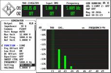
- Distortions of a piece of 1.6mm double sided PCB 1.6mm thick (the first piece I was able to grab from the dumpster) about 15x15 cm in size. 575pF as measured by a handheld impedance meter.
- Distortions of a 470pF/100V styroflex capacitor.
Bottom line, the PCB distortions are under -119dB. Could get lower with multiple air separated shielding, steel box, etc... unfortunately I don't have the means to do this.
So Mr. Marsh, check your setup and do some relevant and consistent measurements. What you did so far is misleading and ultimately incorrect. Having the proper instruments is only half of the story, you also have to know how to use them, estimate error sources, do cross checks, etc...
Sorry, the UPD instrument date is wrong, didn't bother to adjust it 🙂.
Edit: since the file names are invisible, -119dB is the PCB, -118dB is the styroflex cap
Attachments

Last edited:
Are those measurements with the sample in series with the signal? What is the source/load impedance? They look to be the residual of the UPD. All makes sense.
Sent from my SGH-M919 using Tapatalk
Sent from my SGH-M919 using Tapatalk
Are those measurements with the sample in series with the signal? What is the source/load impedance? They look to be the residual of the UPD. All makes sense.
Sent from my SGH-M919 using Tapatalk
Yes, and 10ohm RGen as shown. Input impedance is 20K||200pF (balanced). I should have mentioned, I'm not saying that distortion values are correct as absolute values (the cap impedance at 5KHz is about 63K, so there's definitely a large contribution) but the PCB distortions are not worse than a good quality film cap.
If I connect the UPD generator with the analyzer internally (no cables involved), the distortions go down to -133dB.
Last edited:
waly.... glad you are getting involved. You didnt say what your pcb material is. And, pls look below -119db..... that would not be a great ULDistotion generator level.
I never said what my material was either. But it isnt high quality.... from Radio Shack. What is your pcb ... FR4? G10? What is the DF?
The thd ought to go lower than -119 if it is high quality dielectric... especially from that film capacitor.
THx-RNMarsh
I never said what my material was either. But it isnt high quality.... from Radio Shack. What is your pcb ... FR4? G10? What is the DF?
The thd ought to go lower than -119 if it is high quality dielectric... especially from that film capacitor.
THx-RNMarsh
Last edited:
waly.... glad you are getting involved. You didnt say what your pcb material is. And, pls look below -119db..... that would not be a great ULDistotion generator level.
I never said what my material was either. But it isnt high quality.... from Radio Shack. What is your pcb ... FR4? G10? What is the DF?
The thd ought to go lower than -119 if it is high quality dielectric... especially from that film capacitor.
That's all I can get (-120dB), even with the balanced I/O cabling shorted (no cap). Sorry, I can't do better without a multiple shielding enclosure, which I don't have and have no intend to build. Material is FR4, don't know the source.
Even assuming -120dB is the upper limit of this PCB distortion (which is obviously not), I'll let you calculate how much less distortion is a trace over a ground plane going to have. Hint, about -40dB (assuming the distortions are proportional with the copper area).
And in all truth, I don't care much about. All I was looking for is to show that your measurements are wrong and therefore your conclusions are flawed, yet another episode of scaremongering, typical for the "high end audio".
" yet another episode of scaremongering, typical for the "high end audio"."
I don't think it's scaremongering, it's rather curiosity below -120dB🙂
I don't think it's scaremongering, it's rather curiosity below -120dB🙂
See #4715 ??Based on these preliminary tests.... I would not use either for SOTA designs at ULD levels.
I don't think it's scaremongering, it's rather curiosity below -120dB🙂
Really? To me, it smells like "I use Teflon PCBs for my best designs, since FR4 may have DA, DF, PIM, chicken pox, and some mad cow disease". At -160dB to -180dB distortions for a PCB trace we can also talk about the impact of the universe Big Bang residual microwave radiation on the FR4 material.
Last edited:
Waly, everybody knows that the BEST dielectric is a high tech ceramic that can only be drilled with diamond drills, etc, with gold etching. But we will get along with fortified Teflon PCBs as they are more practical. FR-4? Which one, Waly? All of them, some of them, most of them? '-) JC (Scaremonger in chief)
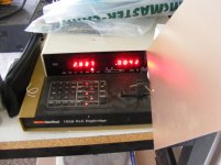
Well I have some FR-4/G10 PC material with 1/2 oz. copper .032" thick 8" x 10" with a dielectric constant of 5.2 at 1 Mhz., dielectric strength of 400V/mil, a dissipation factor of .025 @ 1 Mhz., permitivity at 1 Mhz. of 4.7 maximum, a loss tangent of .015 at 1 Mhz with a volume resistivity of 5e5 mimimum. Test signal 5 Vrms at 5,000 hertz.
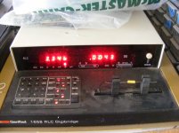
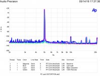
Soldering two leads to it and measuring it with my bridge is shown in the first attachment. A similar MYLAR capacitor is shown in the second. The third are my test results for the AP System 2 residual, PC card, capacitor and 100K resistor.
Soldering two leads to it and measuring it with my bridge is shown in the first attachment. A similar MYLAR capacitor is shown in the second. The third are my test results for the AP System 2 residual, PC card, capacitor and 100K resistor.
Attachments
Last edited:
Well I have some FR-4/G10 PC material with 1/2 oz. copper .032" thick 8" x 10" with a dielectric constant of 5.2 at 1 Mhz., dielectric strength of 400V/mil, a dissipation factor of .025 @ 1 Mhz., permitivity at 1 Mhz. of 4.7 maximum, a loss tangent of .015 at 1 Mhz with a volume resistivity of 5e5 mimimum. Test signal 5 Vrms at 5,000 hertz.
Soldering two leads to it and measuring it with my bridge is shown in the first attachment. A similar MYLAR capacitor is shown in the second. The third are my test results for the AP System 2 residual, PC card, capacitor and 100K resistor.
All I see is the laminate acting as a great antenna (which was my point about multiple shielding being required). Is there anything else I'm missing? Or is this one of the usual "how dumb you all are" charades?
Just looking for the lowest distortion material by any and all available tests and how to measure it. As this isnt about amplifiers per se.... but ultra low distortion generator...... which I tested months ago and it DID require me to put in its own double shielded environment to test the very low residual distortion from Davada's generator .....
JC might have a partial answer to the limit of measuring small C in series with the instruments input (non-linear) C might cause us/me looking at distortion generated by the interface.
What do you think?
THx-RNMarsh
JC might have a partial answer to the limit of measuring small C in series with the instruments input (non-linear) C might cause us/me looking at distortion generated by the interface.
What do you think?
THx-RNMarsh
Last edited:
I think we have a bunch of antennae.
Well Derfy,
What are the antennas picking up and what spectra would you expect? This is one of those side issues that one was not looking for and as a result may miss something that may involve further examination.
is this one of the usual "how dumb you all are" charades?
This is one of those side issues that one was not looking for and as a result may miss something that may involve further examination.
Told'ya.
...If you look at the SYS1 oscillator schematic... around the multiplier output. The is a Mdac there that controls the amount of gain between the multiplier and oscillator...
You mean U251 - the AD7523?
That looks like a frequency fine trim, a computer controlled version of the vernier on the Tek 505.
Have I missed some implications on the multiplier to oscillator gain?
You mean his composite amplifier stuff?... also look at JCX's techniques...
I know the LT "super oscillator" does this but it seems unnecessary complexity.
The Sys 1 uses 5534 op-amps and is already pretty adequate.
A replacement with AD797 should increase the return ratio (feedback) by 20 dB or more.
The 797 is not simple first order so the improvement varies with frequency but I expect that to be sufficient for any reasonable requirement.
Have I overlooked some point?
Any comment JCX?
Best wishes
David
You mean U251 - the AD7523?
That looks like a frequency fine trim, a computer controlled version of the vernier on the Tek 505.
Have I missed some implications on the multiplier to oscillator gain?
You mean his composite amplifier stuff?
I know the LT "super oscillator" does this but it seems unnecessary complexity.
The Sys 1 uses 5534 op-amps and is already pretty adequate.
A replacement with AD797 should increase the return ratio (feedback) by 20 dB or more.
The 797 is not simple first order so the improvement varies with frequency but I expect that to be sufficient for any reasonable requirement.
Have I overlooked some point?
Any comment JCX?
Best wishes
David
Yes your right. It is frequency trim. I thought U251 was tied to the 90 deg phase.
Once the oscillator has settled it doesn't require the full authority of the multiplier. Additional decoupling can be switched in and switched out again if needed. This was done in the ST1700 series. there was a switch on the front panel as well for fast settling or low distortion, In the fast settling mode the multiplier had full authority at all times. In low distortion mode you could here a relay switch once the oscillator had settled.
I was thinking more of JCX's class A arrangement.
Last edited:
The Sys 1 uses 5534 op-amps and is already pretty adequate.
A replacement with AD797 should increase the return ratio (feedback) by 20 dB or more.
The 797 is not simple first order so the improvement varies with frequency but I expect that to be sufficient for any reasonable requirement.
Have I overlooked some point?
Best wishes
David
I think we are trying to do the best possible rather than reasonable or pretty adequate?
But at these low thd levels, even repeatability is a challenge. This morning I had noise all over the place. By this evening, there was less noise.... I could not make it go away until this evening... so maybe there was some EMI/RFI going on. I'd have to throw the spectrum/network analyzer on it to see. Now things have settled down.... but I am 6dB off in THD from just yesterday. ??
I ordered a QA401 because of its bal/diff input and better isolation which I may be able to use to some advantage.
THx-RNMarsh
Last edited:
I ordered a QA401 because of its bal/diff input and better isolation which I may be able to use to some advantage.
THx-RNMarsh
The Faraday cage I made to test Davada's generator was given away by my wife.... she thought it was just a small steel garbage can. Guess I need another one.
THx-RNMarsh
Last edited:
- Home
- Design & Build
- Equipment & Tools
- Low-distortion Audio-range Oscillator