Dave you can build an SVF with your chosen values and test that before going the full length.
Keep in mind that the amplifier is loaded by a capacitor. The distortion tests Samuel and the manufacture did where with resistor loads. A fast op amp like the AD797 might have trouble at such low Z. Even rf oscillations so small that there hard to see on a scope will cause a rise in distortion. Sometimes it's just settling issues.
Keep in mind that the amplifier is loaded by a capacitor. The distortion tests Samuel and the manufacture did where with resistor loads. A fast op amp like the AD797 might have trouble at such low Z. Even rf oscillations so small that there hard to see on a scope will cause a rise in distortion. Sometimes it's just settling issues.
Can't find an option in LTspice for noise on a dB scale.
They don't have a waveform math option (20*log10(Vn))?
I've been slow to post, I do have old refs on "active compensation" and a little experience:
http://electronotes.netfirms.com/EN195.pdf in http://www.diyaudio.com/forums/equi...n-audio-range-oscillator-461.html#post4702488 more recent ref is dangerous in that you really need to look at phase margins, the active compensated integrator barely works with the most boring, practically 90 degree phase margin dominant pole op amps
and of course my hobbyhorse is composite op maps - moar loop gain, isolation of input op amp from load effects, the possibility of heavy internal AB bias in early generation DSL driver output op amps or even using a dual for the output and biasing them against each other for Class A push-pull operation
Not as I understand your comment.
Say the op-amp is 1nV/rtHz and 2 pA/rtHz for a noise impedance of 500 ohms.
If the source is indeed 500 ohms then
noise = rt(1 nV ^2 + (2 pA * 500 ohms) ^2)
= 1.41 nV /rtHz
Now keep the source impedance at 500 ohms but hypothetically reduce the current noise to 1 pA/rtHz, the noise impedance rises to 1 k ohm.
But now noise drops
noise = rt(1 nV ^2 + (1pA * 500 ohms) ^2)
= 1.11 nV /rtHz.
Have I made a mistake?
The resistors hardly become more expensive, too little power to matter.
Even the capacitors for 1 kHz and above barely move in price and size is small.
Only the bottom decade is a bit problematic.
Metalized polypropylene capacitors are cheap so the only problems are bulk and possible unpredictable distortion from the metal spray connections.
I can live with that or just pay for a film/foil capacitor while I wait for MLCC NP0 to improve.
Yes, this is possible so I checked Samuel's op-amp test data (p.24) and the AD797 drives 600 ohms with practically no increase in distortion. That has been the basis of my decision to keep the impedance at around 600.
There is a small loss of gain from the load, need to analyse the trade-off for this.
Best wishes
David
No, you are correct. My mistake about matching noise impedance.
For a given voltage noise op amp, less current noise results in a higher noise impedance and lower overall noise. If you had 1 1nV/rt Hz JFET op amp its noise impedance would approach infinity, and yet it would be wonderful in a 1k or so circuit environment
However, it remains true that seeking a very low voltage noise at the expense of increased current noise to the point that the latter begins to dominate is misguided. I realize that is not really what you are suggesting. You are basically saying to reduce the impedance of the circuit environment to keep noise from input noise current from dominating, while using an op amp that has lower voltage noise and somewhat higher current noise.
That is fine as long as you are comfortable with larger caps and the op amp can drive the heavier load. The lower integrator R-C impedance environment likely will not reduce the noise contribution from the Johnson noise of the tuning resistor, since the resistor sees low Z on both sides of it and the Johnson noise really becomes a noise current. SPICE can be our friend here.
All of this matters if the noise of the integrators is not strongly dominated by some other noise source, such as the agc signal injection. If someone makes the signal voltage across the agc JFET really, really small in pursuit of lower THD from that element, the necessary post amplification needed to achieve adequate multiplier authority can inject more noise into the SVO loop than the integrators. Once again, SPICE can be our friend here.
Cheers,
Bob
Dave you can build an SVF with your chosen values and test that before going the full length.
Keep in mind that the amplifier is loaded by a capacitor. The distortion tests Samuel and the manufacture did where with resistor loads. A fast op amp like the AD797 might have trouble at such low Z. Even rf oscillations so small that there hard to see on a scope will cause a rise in distortion. Sometimes it's just settling issues.
I believe that the op amp is loaded by both the integrator feedback capacitor and the resistor driving the next integrator, both of whose value will typically be the same at the operating frequency if the SVO is designed such that the integrators should have unity gain at the operating frequency. Then the load impedance phase angle would be 45 degrees. In any case, you make a very good point in that it seems possible that the THD of the op amp could be somewhat dependent on the phase angle of a heavy load in some cases (even apart from stability issues).
Cheers,
Bob
10mfd/50vdc met. polycarbonate capacitors are readily available and small size.
See WESCO 32MPC series
-RNM
See WESCO 32MPC series
-RNM
They don't have a waveform math option (20*log10(Vn))?
I'll look later. Work day today.
I believe that the op amp is loaded by both the integrator feedback capacitor and the resistor driving the next integrator, both of whose value will typically be the same at the operating frequency if the SVO is designed such that the integrators should have unity gain at the operating frequency. Then the load impedance phase angle would be 45 degrees. In any case, you make a very good point in that it seems possible that the THD of the op amp could be somewhat dependent on the phase angle of a heavy load in some cases (even apart from stability issues).
Cheers,
Bob
Not to mention take taps for control. I buffered all the taps to avoid additional loading.
One other thing to consider is the half-wave wave-forms on the rails. I would think this would increase from heavy loading of the op amps. PSRR will give us 60 - 70 dB @ 1kHz but we are measuring much lower than this.
I don't know that JCX's offset bias into class A would work for an integrator. Comments?
Would be interesting though.
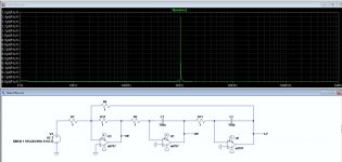
Just a reminder of what I can do here --- this is davids generator, two years ago, using the Faraday shield and battery power also under the shield:

And, I still see differences in pcb material/dielectric.... now with pcb in shield also.
THx-RNMarsh
And, I still see differences in pcb material/dielectric.... now with pcb in shield also.
THx-RNMarsh
Last edited:
Samuel's website has measurements that show the successive reduction of oscillator distortion from the Tek 505 to the Audio Precision System 1, the SYS 2722 and finally the APx555. The System 1 source is quite similar to the Tek 505 except for the computer control requirements. They are both 5534 based State Variable. Anyone worked out how the distortion was reduced?
As far as I know, the main elements are:
SG 505 to System One: Use of a sample-and-hold based level detector, better multiplier, better output driver
System One to System Two: Use of relays to switch the integrator capacitors instead of JFETs
System Two to APx555: Switch from film to ceramic C0G integrator capacitors, use of composite opamps
Samuel
Just a reminder of what I can do here --- this is davids generator, two years ago, using the Faraday shield and battery power also under the shield:
View attachment 549618
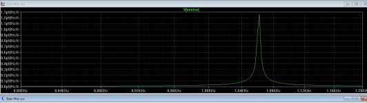
Interesting, how did you attenuate/filter the 1k fundamental (I suppose at least 1V) to -140dB while not affecting the harmonics? 50-60-70-80dB attenuation is usual, the rest to the noise floor is the analyzer dynamic range.
Anything else is irrelevant. With synchronous (or time, if you prefer) averaging, if enough time is allowed, one could bring the noise floor to the background noise of the universe.
From where I sit, you don't have to wipe the egg off your face with the PCB dielectric measurements.
Edit: -170dB noise floor with a 16bit HP boat anchor that you could get today for about the same price as an average sound card: http://www.diyaudio.com/forums/soli...tware-thd-sine-generating-13.html#post4170130
Last edited:
As far as I know, the main elements are:
SG 505 to System One: Use of a sample-and-hold based level detector, better multiplier, better output driver
System One to System Two: Use of relays to switch the integrator capacitors instead of JFETs
System Two to APx555: Switch from film to ceramic C0G integrator capacitors, use of composite opamps
Samuel
So is the sys2722 family the odd man out? I understand it has lower distortion than the newer APx555.
Jan
Interesting, how did you attenuate/filter the 1k fundamental (I suppose at least 1V) to -140dB while not affecting the harmonics? 50-60-70-80dB attenuation is usual, the rest to the noise floor is the analyzer dynamic range.
yes, the notch is very deep. You can check out that info talked a lot around here regarding the ShibaSoku 725 for your answer.
or check with Audio Precision.
THx-RNMarsh
Last edited:
Original sample of pcb looks like a brown material (phenolic?) vs an FR4. The phenolic changes C by -11% from 100Hz to 100KHz. While the FR4 changes -3%. The Df is X10 lower from 100-100KHz with FR4.
THx-RNMarsh
THx-RNMarsh
Original sample of pcb looks like a brown material (phenolic?) vs an FR4. The phenolic changes C by -11% from 100Hz to 100KHz. While the FR4 changes -3%. The Df is X10 lower from 100-100KHz with FR4.
THx-RNMarsh
The brown stuff is usually a paper impregnated with a phenolic resin. Cheap but as you measured not very good. Still used for some low end products such as remote controls.
Nice work.
or check with Audio Precision.
Thanks for the explanation, very enlightening.
As far as I know, the main elements are:
SG 505 to System One: Use of a sample-and-hold based level detector, better multiplier, better output driver
System One to System Two: Use of relays to switch the integrator capacitors instead of JFETs
System Two to APx555: Switch from film to ceramic C0G integrator capacitors, use of composite opamps
Thank you, very helpful.
The effect of the S&H level detector improvement looks to be visible in your data.
I will study the multiplier improvement.
Better output driver I have already worked out.
I never planned to use JFET switches anyway.
Already planned to use NP0, except maybe bottom decade.
So all under control except for the composite op-amps, which I can keep for a version 2 improvement if needed.
Did you ever confirm the op-amp selection for the 2722 and APx555?
So is the sys2722 family the odd man out? I understand it has lower distortion than the newer APx555.
The SYS2722 is one model of the System 2 family, there's a discontinued products list at AP to sort this out.
Samuel's data shows distortion is somewhat lower than the APx555 only at lower frequencies, < 3 kHz.
Best wishes
David
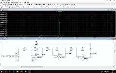
For comparison same values with an OPA827
Either I seriously misunderstand or there's some problem.
The noise is much lower than an AD797 despite the fact the OPA827 has more than 10 dB worse volt noise specification?
That's far too much to explain with current noise at that impedance.
Best wishes
David
- Home
- Design & Build
- Equipment & Tools
- Low-distortion Audio-range Oscillator