Interesting, how did you attenuate/filter the 1k fundamental (I suppose at least 1V) to -140 dB while not affecting the harmonics?
As most "serious" analog analyzers they use an auto-tune circuit for the notch. See e.g. CordellAudio.com - Build a High Performance THD Analyzer.
Did you ever confirm the op-amp selection for the 2722 and APx555?
No.
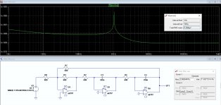
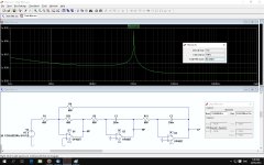
I tried ploting 20*log(V(onoise)) but the result doesn't make sense.
Simply switch the Y axis to logarithmic, and use an appropriate range (e.g. 1 nV/rtHz to 100 nV/rtHz).
Noise very close to the fundamental is not of much interest, as it is supressed by the leveling loop and the notch filter of the analyzer.
Samuel
Regarding the voltage coefficient of PCB stray capacitance: I've investigated this years back, but decided to quickly look at it again with an improved measurement setup due to the recent discussion in this thread.
Using a bridge optimized for capacitor distortion measurements (details will be disclosed later this year), I've measured a standard FR-4 board with 130 pF stray capacitance at 8.16 kHz. With +20 dBu across the PCB capacitance, I see no 2nd harmonic (noise floor at less than -140 dB), and -122.8 dB 3rd harmonic. Higher harmonics all below the noise floor.
The mentioned numbers are for a model where distortion appears as a voltage source in series with the capacitor.
Now let's see how this relates to an actual distortion contribution in a circuit. Let's say we have a circuit node with 10 kOhm impedance, 10 pF stray capacitance and a voltage swing of +20 dBu. Using the equivalent circuit, the 3rd harmonic distortion is high-pass filtered with a 1st-order filter with 1.59 MHz corner frequency. So harmonic distortion at e.g. 15.9 kHz (5.3 kHz fundamental) is attenuated by 40 dB, so we get an effective distortion source of -162.8 dB.
Now the mentioned circuit conditions are highly unlikely to occur in a low distortion circuit; either the node impedance is much lower (opamp output), the voltage swing near zero (opamp virtual earth), or at least careful layout techniques would reduce the stray capacitance by an order of mangitude. Likely this would put the effective distortion contribution to at least -180 dB if not -200 dB.
A note on the credibility of my measurement: My setup has certain limitations when operated with just 130 pF (it is optimized for 10-100 nF). I've quickly put in a comparable Polystyrene capacitor, and it showed almost the same 3rd harmonic distortion. So possible we're still looking at measurement setup limitations.
Samuel
It seems to me the more critical issue of laminate distortion would be where there is a DC potential.
C=q/V C dv/dt + V dc/dt = i.
So there could be a vibration induced current on signal lines placed above or below a power plane.
C=q/V C dv/dt + V dc/dt = i.
So there could be a vibration induced current on signal lines placed above or below a power plane.
It seems to me the more critical issue of laminate distortion would be where there is a DC potential.
C=q/V C dv/dt + V dc/dt = i.
So there could be a vibration induced current on signal lines placed above or below a power plane.
Who would place signal lines above or below power planes?
Regarding the voltage coefficient of PCB stray capacitance: I've investigated this years back,
Using a bridge optimized for capacitor distortion measurements (details will be disclosed later this year), I've measured a standard FR-4 board with 130 pF stray capacitance at 8.16 kHz. With +20 dBu across the PCB capacitance, I see no 2nd harmonic (noise floor at less than -140 dB), and -122.8 dB 3rd harmonic. Higher harmonics all below the noise floor.
Now the mentioned circuit conditions are highly unlikely to occur in a low distortion circuit; either the node impedance is much lower (opamp output), the voltage swing near zero (opamp virtual earth), or at least careful layout techniques would reduce the stray capacitance by an order of mangitude. Likely this would put the effective distortion contribution to at least -180 dB if not -200 dB.
Samuel
Thank you for looking into this for us.
That is impressive tests on such low C. Using the traditional analyzers that I have, the 100K Z and the noise increase limited my tests. But also the generator distortion from my analyzer or external ones is too high (!) to see any contribution by pcb. I need a better generator and hope something can be made from one here.
Regarding the C and Z of nodes.... yes for IC opamps. However, in other audio apps where discrete circuitry is used, we are exposed to the high Z nodes (Vas etal) in amps and filters and converters. Thus, the choice to use 100K. In higher voltage circuits (eg power amp) being measured, it could start to be a limiting factor. I have already attempted to measure some amazing prototype amps with extremely low thd. Still wondering what our limitations (besides knowledge) will be.
What THD limitation is imposed by the test system which uses a non-linear input C from a jFET front end with similar DUT C value in series? An interfacing issue.
THx-RNMarsh
Last edited:
I would hope that the noise models for these opamps are solid, but know that distortion modeling is not. Does anyone have any sort of validation wrt this? (Noise model vs measurements)
At least davada's sims seem to match the datasheets more closely.
At least davada's sims seem to match the datasheets more closely.
I would hope that the noise models for these opamps are solid, but know that distortion modeling is not. Does anyone have any sort of validation wrt this? (Noise model vs measurements)
At least davada's sims seem to match the datasheets more closely.
Only if the spice model explicitly says about modelling the noise performance (they usually do, for devices with guaranteed noise performance). Otherwise, 99% percent of the commonly available opamp models are stupid macromodels, good for AC analysis only. I've seen such macromodels that were unable to correctly simulate a DC servo!
If I recall correctly, a notable exception is the LME49710/LM4562 model, which is component level.
Ad797, OPA827 on a log scale.
Not sure about LTSpice, but in my simulator it is NTOT(ONOISE) where ONOISE is the output node as defined in the .NOISE macro.
Who would place signal lines above or below power planes?
4 layer boards.
Not sure about LTSpice, but in my simulator it is NTOT(ONOISE) where ONOISE is the output node as defined in the .NOISE macro.
In LTspice it's V(onoise).
Last edited:
4 layer boards.
Yes I know but who would do this in a ULD design. Seems like asking for trouble and not just because of PCB dielectric.
Yes I know but who would do this in a ULD design. Seems like asking for trouble and not just because of PCB dielectric.
My view is that power planes allow very low impedance power distribution and with local decoupling should have advantages. My low noise preamp is 4 layers.
Only if the spice model explicitly says about modelling the noise performance (they usually do, for devices with guaranteed noise performance). Otherwise, 99% percent of the commonly available opamp models are stupid macromodels, good for AC analysis only. I've seen such macromodels that were unable to correctly simulate a DC servo!
If I recall correctly, a notable exception is the LME49710/LM4562 model, which is component level.
Try boot strapping the power pins. For some op amp models it just not possible.
My view is that power planes allow very low impedance power distribution and with local decoupling should have advantages. My low noise preamp is 4 layers.
I thinking about cross talk from plane to signal trace.
From Samuel's comments it sounds like PCB C parasitic is a non issue anyway.
There is a difference between the PCB capacitance and the vibration induced current in a capacitor.
As I think Samuel has found at low voltage levels there is no buckling in the capacitor's dielectric. This can occur at higher voltages. The mechanical motion between the plates creates a signal current.
I use 25 farads of filter capacitance at the power entry point and 10 uF ceramic at each power pin in my preamp.
Try boot strapping the power pins. For some op amp models it just not possible.
Yes, some models are drawing a constant current from the supplies, disregarding the load current. Other model the supply current by Io=Vo/Ro where Ro is the real part of the output impedance. That's worse, since it may create the illusion that it actually works. In general, with a very few exceptions, modelling a large signal parameter like distortion is moot in opamps.
Paying customers like my organisation get very detailed encrypted models, targeted to certain simulators (usually not Spice based). They are embedded in the macro cells of the design system.
Yes I know but who would do this in a ULD design. Seems like asking for trouble and not just because of PCB dielectric.
4-layer boards are good, but there is no need for power planes to fill the whole area of the board. They can certainly be carved out for critical areas. Ground planes are much more important, but even they can be carved out in selected areas. Finally, power planes and ground planes, used blindly, are not always the answer to the maiden's prayer. Sometimes you want better control of where the currents flow.
Cheers,
Bob
Paying customers like my organisation get very detailed encrypted models, targeted to certain simulators (usually not Spice based). They are embedded in the macro cells of the design system.
Yes we supply encrypted full top level Mextram models to serious customers in HSPICE which is not terribly different. Big sparse matrix solvers are not that fundamentally different from each other sometimes it is just syntax and supported features.
- Home
- Design & Build
- Equipment & Tools
- Low-distortion Audio-range Oscillator