DA linear model tells how Z varies with frequency, gives "funny looking" time response - but is not evidence of a nonlinear system, doesn't introduce new frequency components, harmonics or IMD/PIM
if Z varies with V then you have a nonlinear system, as with dielectric constant having V coefficient in hi K ceramic cap formulations
if Z varies with V then you have a nonlinear system, as with dielectric constant having V coefficient in hi K ceramic cap formulations
Samuel's website has measurements that show the successive reduction of oscillator distortion from the Tek 505 to the Audio Precision System 1, the SYS 2722 and finally the APx555.
The System 1 source is quite similar to the Tek 505 except for the computer control requirements.
They are both 5534 based State Variable.
Anyone worked out how the distortion was reduced?
Is it mainly improvements in the leveler subsystem?
The Sys 1 has a unity gain inverter compared to the Tek 505 where the gain is closer to (-)2, not sure the reason for that.
I can't find the schematics of the 2722 or APx555.
I recall claims they are AD797 based rather than 5534, which makes sense but I haven't confirmed this.
It would be helpful not to reinvent the wheel, so anyone have any information on the later products?
David
Dave I have much better understanding of the SYS One oscillator because that's the one I studied the most when designing my own.
I think Samuel summarized it best by pointing out some of more subtle things that were done to maximize performance. There is more to a ULD oscillators than what you may have considered. One of which is the compensation of the 5534. It looks a lot like 2 pole compensation. Another is the RC filtering of power sources. Pre charging of the capacitors.
If you look at the SYS1 oscillator schematic you will a lot going on around the multiplier output. The is a Mdac there that controls the amount of gain between the multiplier and oscillator. The Mdac can be use two different ways. Either as a voltage output or current out depending on whether the output is used as the input or the reference is used as input.
The is also a start up speed up circuit that bypasses the multiplier and adds more gain when needed. This allows for a lot more decoupling between the multiplier and oscillator.
There is also a clamping/limiting circuit around the integrators. This keeps the oscillator level within the authority of the multiplier and the control loop gain during range changes or other disturbances. It also allows for additional multiplier decoupling.
In the 505 Bruce used a technique from one of his patents. A Jfet is used to inject a bit of error signal into the inverting input of a non amplifier canceling some of the distortion. You can look up the patent for details.
Look for the subtleties in his designs. That's where his secrets are.
Some more maybe controversial things like ripple in the control signal. I have show that at least in the HP339A distortion reduction from illuminating control signal ripple. But of course this depends on many things. Mostly the multiplier's sensitivity to Vc ripple. Isolation of switching signal if used is must. Shunt regulator help with this.
The rest is layout.
You might also look at JCX's techniques for reducing amplifier distortion.
Last edited:
DA linear model tells how Z varies with frequency...but is not evidence of a nonlinear system...
if Z varies with V then you have a nonlinear system...
Yes, but what sparked my curiosity is the apparent correlation between the two properties.
NP0, at one extreme, has both low DA and low distortion.
The poorer dielectrics usually have both more DA and more distortion.
Best wishes
David
...Samuel summarized...One of which is the compensation of the 5534. It looks a lot like 2 pole compensation.
Yes, but Samuel's comments were for the Tek 505.
So I already know 2 pole compensation and the other ideas.
My question was how does the Sys1 improve on this?
Look for the subtleties....
Oh yes, hence my questions😉
Best wishes
David
DA linear model tells how Z varies with frequency, gives "funny looking" time response - but is not evidence of a nonlinear system, doesn't introduce new frequency components, harmonics or IMD/PIM
if Z varies with V then you have a nonlinear system, as with dielectric constant having V coefficient in hi K ceramic cap formulations
yes. I think we know this. All tests mentioned are to get an over-view of the quality of the dielectric material used in the pcb.
Would time response 'sound' different when changed?
THx-RNMarsh
Last edited:
Yes, but what sparked my curiosity is the apparent correlation between the two properties.
NP0, at one extreme, has both low DA and low distortion.
The poorer dielectrics usually have both more DA and more distortion.
Best wishes
David
😎🙂... yes.
-RM
In the 505 Bruce used a technique from one of his patents. A Jfet is used to inject a bit of error signal into the inverting input of a non amplifier canceling some of the distortion. You can look up the patent for details.
The rest is layout.
You might also look at JCX's techniques for reducing amplifier distortion.
This seems very much like what is done in later Krohn-Hite low distortion generators.
Have you seen their schematics?
-RM
Last edited:
Neither can you. Certainly not from anything presented here. You'll never let go of the myth that DA means distortion so be it. Same as DBT listening, too much to lose.
Look Scott.... I never said DA = harmonic distortion... that is your myth.
Da, Df and THd of the pcb dielectric all are good useful data for sorting and finding the best materials.
THx-RNMarsh
Last edited:
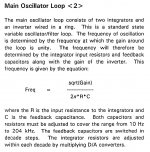
Dave what are calling a gain of minus two in the 505. Are you referring to the ratio of R1517 and R1512?
If these resistances are equal then fc = 1/2PIRC.
If not equal then fc = sqrt(gain) / 2PIRC
The 505 also has the frequency vernier and there is additional feedback through R1609, R1519, R1516. And other funky stuff.
If these resistances are equal then fc = 1/2PIRC.
If not equal then fc = sqrt(gain) / 2PIRC
The 505 also has the frequency vernier and there is additional feedback through R1609, R1519, R1516. And other funky stuff.
Last edited:
Yes, but Samuel's comments were for the Tek 505.
So I already know 2 pole compensation and the other ideas.
My question was how does the Sys1 improve on this?
Oh yes, hence my questions😉
Best wishes
David
Much of Samuel's comments on the 505 also apply to the sys1 as well.
The multiplier for one and the sampled peak detector are the two biggest improvements.
This seems very much like what is done in later Krohn-Hite low distortion generators.
Have you seen their schematics?
-RM
I have them.
I just remembered the jfet trick is in the post amplifier stage not the oscillator.
yes... near/at the output. same trick, isnt it?
Did they make use of the patent or does the patent only apply to an oscillator?
-RM
Did they make use of the patent or does the patent only apply to an oscillator?
-RM
Last edited:
yes... near/at the output. same trick, isnt it?
Did they make use of the patent or does the patent only apply to an oscillator?
-RM
The patent cover all uses and any device other than a Jfet. Any amplifier.
In the patent the jfet is just an simple amplifier.
I not sure these old tricks will work with our sota modern op amps.
The input bias current canceling techniques get messed up using the old methods like balancing input resistances etc. It's been suggested that it may even elevate distortion and cause offset rather than curing them.
The input bias current canceling techniques get messed up using the old methods like balancing input resistances etc. It's been suggested that it may even elevate distortion and cause offset rather than curing them.
Here it is Richard.
I was wrong. It's for an inverting amplifier.
Patent US4296381 - Distortion reduction circuit for an inverting feedback amplifier - Google Patents
I was wrong. It's for an inverting amplifier.
Patent US4296381 - Distortion reduction circuit for an inverting feedback amplifier - Google Patents
Dave...to the ratio of R1517 and R1512?
R1517 and R1612 I think - it's a poor typeface.
As you say, there's a bit of other stuff but it's about a factor of 2.
This does determine the frequency but also makes the V at the integrators unequal, not quite optimal for THD + N.
The Sys 1 has R2502 and R3504. also a bit of other stuff for frequency trim but close to 1.
Best wishes
David
I went with the unity gain. The Mdacs are precision devices. The caps are matched so the output levels are very close to same.
Here it is Richard.
I was wrong. It's for an inverting amplifier.
Patent US4296381 - Distortion reduction circuit for an inverting feedback amplifier - Google Patents
very clever...... thx
-RM
- Home
- Design & Build
- Equipment & Tools
- Low-distortion Audio-range Oscillator