Here are the scheme and diagram of ADAU1452 and AD1938 (both from Lusya).
Microsoft OneDrive - Access files anywhere. Create docs with free Office Online.
You CAN use the AD1938 CODEC with ADAU1466 or any ADAU board, even the old ADAU1701.
Microsoft OneDrive - Access files anywhere. Create docs with free Office Online.
You CAN use the AD1938 CODEC with ADAU1466 or any ADAU board, even the old ADAU1701.
Here are the scheme and diagram of ADAU1452 and AD1938 (both from Lusya).
Microsoft OneDrive - Access files anywhere. Create docs with free Office Online.
You CAN use the AD1938 CODEC with ADAU1466 or any ADAU board, even the old ADAU1701.
This is great, thanks! Exactly what I was looking for
And thanks for confirming the compatibility, which is also clear from the documents you just shared
I'm now using a MediaWorks ADAU1467 core board from AliExpress, and a Sure programmer.
Going with the more stripped down board means I can play later with different DACs etc more easily, but more importantly I can easily run multiple digital inputs at the same time. (2 x USB, SPDIF is a minimum, but I also wanted Bluetooth. I'll probably add 1 analogue input).
sorry to bother you again @xplo5iv (I'm pinging you on the thread instead of PM, since I hope it might help others)
I'm still trying to figure out if I want to get an ADAU1542 board or the ADAU1466/67 ones. The former already has SPDIF and RCA connectors for SPDIF (even if only 96KHz SPDIF)
Now, granted, an RCA connector for the coax SPDIF is easy to add. When it comes to SPDIF, though, the only one I found that can support high enough data rates is the Blocked receiver and possible the Blocked as a transmitter. Which would also require a separate PCB for the couple of passive components needed
Since you mention you plan to use SPDIF input on the ADAU1467 board with no SPDIF transceiver, do you have suggestions for the SPDIF optical transceivers?
Anyone else?
In a way, since I need to add components to the board, maybe using an SPDIF to I2S converter (usually available for around $10) to the ADAU1452 is also a solution, if I ever decide that I need 192KHz SPDIF. For 96KHz SPDIF, all I need is already on the ADAU1452
@robca TBH I haven't yet sorted SP/DIF on the ADAU1467, I'm still running the ADAU1452.
I've had a problem with being able to save values (e.g. vol control position) into EEPROM when also using selfboot.
To get around this I've just got a 2nd EEPROM, but not got it installed yet. (piggyback, with CS to a different pin)
I've had a problem with being able to save values (e.g. vol control position) into EEPROM when also using selfboot.
To get around this I've just got a 2nd EEPROM, but not got it installed yet. (piggyback, with CS to a different pin)
Thanks again.
I did some more looking around, and it looks as if the easiest to get SPDIF Tx/Rx module working at 16-25MBps is the Aixin DLR2180/DLT2180. I'm adding this info here for future reference. Alas, no datasheet seems to be available
To handle 24bit 192KHz SPDIF, the optical modules must be able to handle ~15MHz, and some of the older chips either top out at 12MHz and have reliability issues working at higher speeds, or are 5V devices that will damage the ADAU input. Of the commonly used optical modules, the only ones easy to source on Aliexpress are the Aixin. There are Everlight modules that would work, but most are backordered from Mouser/Digikey, leaving the Aixin as the only practical option for a hobbyist
Aixin Optoelectronics Technology
and Aixin Optoelectronics Technology
Given that I'm unlikely to need more I/O pins than the ADAU1452 offers, and given that in a pinch I could always get a SPDIF-to-I2S module, probably the ADAU1452 is the best board for me at this stage.
I'm also pretty sure that for the type of sources I use, 24bit 96KHz is probably more than enough, and 192KHz overkill
Get the 1452, it's a powerful chip.
You can get the Lusya from Aliexpres or, if you know someone in Russia, you can get the chipdip.ru version.
Cheers.
You can get the Lusya from Aliexpres or, if you know someone in Russia, you can get the chipdip.ru version.
Cheers.
I finally started playing with the Lusya ADAU1452/AD1938 boards, thanks for the help provided so far. When looking at new devices, I always try to understand the circuit fully, because usually that helps in figuring out what a board can do
I started from the manufacturer schematic and PCB, provided in this forum. The ADAU1452 circuit is identical to the PCB, while the schematic for the AD1938 codec board is not the same as the PCB. I was struggling to understand how is it possible than an AD1938 could support multiple I2S and conversion frequencies by changing a jumper (JP3: 1-3 close for 96KHz I2S, 1-2-3 close for 48KHz I2S, 1-2-3 open for 48KHz TDM, and finally 2-3 close for 96/192KHz TDM and 192KHz I2S). The similar Analog Digital ADAU1452 Eval board requires HW modifications and SPI programming to change how the AD1938 works.
Then I finally realized that IC16 must be a programmed microprocessor that sends the correct configuration to the AD1938 based on JP3, and using the SPI pins on the AD1938 (pins that, in the schematic, are shown as connected to GND, which is most definitely not the case)
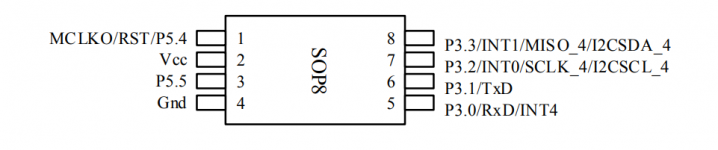
The chip used is part of the STC8F1K08S2 family (using an 8 bit 8051 core, more than enough for sending SPI configuration to another chip), and the specs can be found here STC8F1K08S2 DATASHEET, full programming documentation for he chip are here http://www.stcmicro.com/datasheet/STC8F-en.pdf. I'm including also the pinout for the specific chip used in the codec board
What is interesting is that in the future it's possible to easily remove the STC microprocessor and use the pads to connect the STTM32F103 on the main board to the SPI pins of the AD1938. The STM32 onboard breaks out a secondary SPI port plus 4 generic I/O pins (marked as RX/TX1 and RX/TX2, and those can easily be used for the AD1938, while the ADAU1452 is already connected to the primary SPI port on the STM32. So it would be easy to use the onboard STM32 to program both the ADAU1452 and AD1938.
One of the things I would like to do once I learn more, is to have the ADAU1452 work at the same frequency as the I2S signal. At the moment, the ADAU1452 uses the ASRC to ensure that any I2S signal can be converted to the internal frequency. When using a USB to I2S interface that supports multiple formats, there can be conversion artifacts, especially upconverting 44.1KHz to 48KHz (or multiples). Ideally, if the source is encoded at 44.1KHz, the best option is to use the ADAU1452 and AD1938 at 44.1KHz as well. We could use the MCLK signal from a board like the Amanero Combo384, but changing the core frequency on the ADAU1452 requires a reboot. Using the STM32 to properly reboot the ADAU1452 and set the correct values for the signal frequency would make it possible
When I have a quiet moment, I will capture the SPI signals between the STC micro and the AD1938, to see what settings the manufactures is using for the various AD1938 frequencies. Since it requires having a logic analyzer on a running circuit (and in the lower board), I need to make sure I don't fry the STC chip, because that would be next to impossible to replace (even assuming I can find the right STC chip and buy the programmer, there would be no way to get the source code for that chip)
I started from the manufacturer schematic and PCB, provided in this forum. The ADAU1452 circuit is identical to the PCB, while the schematic for the AD1938 codec board is not the same as the PCB. I was struggling to understand how is it possible than an AD1938 could support multiple I2S and conversion frequencies by changing a jumper (JP3: 1-3 close for 96KHz I2S, 1-2-3 close for 48KHz I2S, 1-2-3 open for 48KHz TDM, and finally 2-3 close for 96/192KHz TDM and 192KHz I2S). The similar Analog Digital ADAU1452 Eval board requires HW modifications and SPI programming to change how the AD1938 works.
Then I finally realized that IC16 must be a programmed microprocessor that sends the correct configuration to the AD1938 based on JP3, and using the SPI pins on the AD1938 (pins that, in the schematic, are shown as connected to GND, which is most definitely not the case)
The chip used is part of the STC8F1K08S2 family (using an 8 bit 8051 core, more than enough for sending SPI configuration to another chip), and the specs can be found here STC8F1K08S2 DATASHEET, full programming documentation for he chip are here http://www.stcmicro.com/datasheet/STC8F-en.pdf. I'm including also the pinout for the specific chip used in the codec board
What is interesting is that in the future it's possible to easily remove the STC microprocessor and use the pads to connect the STTM32F103 on the main board to the SPI pins of the AD1938. The STM32 onboard breaks out a secondary SPI port plus 4 generic I/O pins (marked as RX/TX1 and RX/TX2, and those can easily be used for the AD1938, while the ADAU1452 is already connected to the primary SPI port on the STM32. So it would be easy to use the onboard STM32 to program both the ADAU1452 and AD1938.
One of the things I would like to do once I learn more, is to have the ADAU1452 work at the same frequency as the I2S signal. At the moment, the ADAU1452 uses the ASRC to ensure that any I2S signal can be converted to the internal frequency. When using a USB to I2S interface that supports multiple formats, there can be conversion artifacts, especially upconverting 44.1KHz to 48KHz (or multiples). Ideally, if the source is encoded at 44.1KHz, the best option is to use the ADAU1452 and AD1938 at 44.1KHz as well. We could use the MCLK signal from a board like the Amanero Combo384, but changing the core frequency on the ADAU1452 requires a reboot. Using the STM32 to properly reboot the ADAU1452 and set the correct values for the signal frequency would make it possible
When I have a quiet moment, I will capture the SPI signals between the STC micro and the AD1938, to see what settings the manufactures is using for the various AD1938 frequencies. Since it requires having a logic analyzer on a running circuit (and in the lower board), I need to make sure I don't fry the STC chip, because that would be next to impossible to replace (even assuming I can find the right STC chip and buy the programmer, there would be no way to get the source code for that chip)
Attachments
Last edited:
I connected my logic analyzer and captured the output from the SCL microprocessor. As expected, it uses SPI to send data to all 17 registers inside the AD1938. Weirdly it sends the same data twice. Then the SCL microprocessor stops sending data, since the AD1938 is initialized.
Changing the JP3 jumper changes data as expected, but only 4 registers actually see any change. And even if the document lists two options for 48kHz setting (one I2S, one TDM), as far as I can tell, 1-2-3 open or 1-2-3 close have the exact same effect, and send the same data
I'm including a PDF with the data sent to each register, and my own interpretation of it using the AD 1938 datasheet. I highlighted the changed registers
Last edited by a moderator:
Turns out I made a mistake yesterday, and I didn't properly close all 3 pins (1-2-3 close in the AD1938 PCB PDF). If only 1-2 are closed, the SCL microprocessor reads it the same as 1-2-3 open (the circuit originally would have recognized this configuration, but since R42 and R126 are not installed, pin 2 floats and likely doesn't produce a different reading.I connected my logic analyzer and captured the output from the SCL microprocessor. As expected, it uses SPI to send data to all 17 registers inside the AD1938. Weirdly it sends the same data twice. Then the SCL microprocessor stops sending data, since the AD1938 is initialized.
Changing the JP3 jumper changes data as expected, but only 4 registers actually see any change. And even if the document lists two options for 48kHz setting (one I2S, one TDM), as far as I can tell, 1-2-3 open or 1-2-3 close have the exact same effect, and send the same data
I'm including a PDF with the data sent to each register, and my own interpretation of it using the AD 1938 datasheet. I highlighted the changed registers
Since it seemed strange that the 1-2-3 close and open sent the same data, today I reconnected the logic analyzer and this time I properly shorted all 3 pins. And I got a different reading for the 48kHz I2S configuration, as it should be.
I'm attaching a new PDF. I did not find a way to remove the old, wrong PDF. Can an admin/moderator delete the previous PDF, please?
Attachments
Hi all
Can anyone help me out?
Got this board recently and hooked up a Sure ICP via I2C to program it.
Made a quick demo and uploaded to the board - it works! And the performance is much better than expected.
I had the issue that I couldn't get it to save to the EProm. Tried uploading via the DSP. I looked at the schematic and saw that my boards resistors corresponded to the SPI configuration so I selected to upload via SPI from the DSP. Still Didn't work.
THEN I changed the USB block to SPI on the EProm, this doesn't seem like it would change anything but it seems I successfully wiped the EProm. Trouble is my board now boots into an error condition. Help!!!
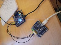
Pics below.
Cheers.
Can anyone help me out?
Got this board recently and hooked up a Sure ICP via I2C to program it.
Made a quick demo and uploaded to the board - it works! And the performance is much better than expected.
I had the issue that I couldn't get it to save to the EProm. Tried uploading via the DSP. I looked at the schematic and saw that my boards resistors corresponded to the SPI configuration so I selected to upload via SPI from the DSP. Still Didn't work.
THEN I changed the USB block to SPI on the EProm, this doesn't seem like it would change anything but it seems I successfully wiped the EProm. Trouble is my board now boots into an error condition. Help!!!
Pics below.
Cheers.
Attachments
Power on the board with jumper shorting two pins on the 3 pin header that are closer to the i2c header- Then I2c for adau and spi for eeprom and upload it via dsp.
Thanks for the response, this doesn't work and I think it's because I'm using the Sure ICP3 which is I2C only. Surely that means trying to set the E2Prom connection in the USB block to SPI is Invalid?
As in, are we trying to load the data into the E2Prom directly from the USB device? Or have I misunderstood?
I'm currently trawling the datasheet to work out how to operate the chip manually from SigmaStudio, I think if I can do that then I can get the 1452 into a state which it is capable of receiving the program by itself.
How does the startup register control relate to the program designed in SigmaStudio?
Have you tried the instructions in post 153 of this thread?
Although it says 1467, I've also got a 1452 and it works fine with the Sure programmer
Connection is SPI via DSP
Although it says 1467, I've also got a 1452 and it works fine with the Sure programmer
Connection is SPI via DSP
Last edited:
Would that work for the Lusya 1452 board? I see that you are using the MediaWorks one.
Edit: The schematic files I have don't agree on whether pin 3 of the main pin header is reset...
Edit: The schematic files I have don't agree on whether pin 3 of the main pin header is reset...
Last edited:
I have Lusya board and Sure ICP3. Have you put jumper on the pins 1 and 2 of SIP1 header before powering the board?
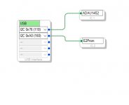
In USB block: ADAU1452-I2C 0x76, E2prom-SPI 0x1 (in "properties" set to SPI Mode 3). Write latest compilation through DSP
In USB block: ADAU1452-I2C 0x76, E2prom-SPI 0x1 (in "properties" set to SPI Mode 3). Write latest compilation through DSP
Attachments
Last edited:
Would that work for the Lusya 1452 board? I see that you are using the MediaWorks one.
Edit: The schematic files I have don't agree on whether pin 3 of the main pin header is reset...
I have a Lusya 1452, Mediaworks 1467 & 1701 and a Sure 1701
I can program them all with the Sure programmer, the 1710 direct and the others via DSP
If you're still stuck later I'll try and take a look at the 1452 to confirm my exact connections and config
Last edited:
Clarifying #173 - connections
Realised an earlier post was ambiguous,so I'll more put details here.
On both Lusya 1452 and MW 1467 connection to the DSP is i2c, connection to eeprom is SPI as it's via the DSP
On both the MW and Sure 1701 both DSP and eeprom are i2c, and is direct to the eeprom, as the DSP lacks the capability
Realised an earlier post was ambiguous,so I'll more put details here.
On both Lusya 1452 and MW 1467 connection to the DSP is i2c, connection to eeprom is SPI as it's via the DSP
On both the MW and Sure 1701 both DSP and eeprom are i2c, and is direct to the eeprom, as the DSP lacks the capability
Thanks guys for clearing it up! This morning I unplugged everything and started a fresh project, booted with the jumper on the self-boot header and uploaded my program. It worked. Wrote to the E2Prom and checked the E2Prom memory - Succeeded!
My test program is a 2khz generator fed to the output. I saw the tone on ARTA but then.. it turned off. Then back on again, then off etc. Not sure what the problem is now, perhaps the board is encountering an error and resetting itself.
My test program is a 2khz generator fed to the output. I saw the tone on ARTA but then.. it turned off. Then back on again, then off etc. Not sure what the problem is now, perhaps the board is encountering an error and resetting itself.
I ordered the board with coax SPDIF in and toslink in and out.
Along with the codec board. Just to have something to start with.
Along with the codec board. Just to have something to start with.
- Home
- Source & Line
- Digital Line Level
- low cost ADAU1452 China board...