Why don't you take the B&O/HifiBerry Beocreate or freeDSP Aurora as reference? Sigma Studio project files should be open source.What would really help is a Sigma Studio file with SPDIF input, I²S input and the routing to and from the ASRC.
Also SPDIF output and I²S outputs (two at least).
The thing is that I am reasonably good at making PCB's, but I lack alot in the theory/science behind digital signals.
I don't have the time to learn that, but I figured that a motherboard with SPDIF (coax or bnc) and I²S in and out would interest people knowing that stuff but maybe lacking the experience in designing PCB's.
I will put the end result up as open hardware if it works as expected.
I have zero interest in monetary gain or prestige on this.
It's something I want, and maybe others as well.
Edit: I would like to design it around the ADAU1452/ADAU1466 Core Boards as they are reasonably priced and very available.
Hello, such board would really be nice. The spacing of the connectors is unfortunately not fitting on to normal pre drilled boards 🙁.
I am using it as IS2 receiver from a raspi with volumio and feed 2 elektor D/As with PCM1794. As a Xover ( actually in combination with a subwoofer )
Hi,
What would really help is a Sigma Studio file with SPDIF input, I²S input and the routing to and from the ASRC.
Also SPDIF output and I²S outputs (two at least).
Preferably with a comment about what pin is used from the "Core Boards".
Sorry but I am not letting anyone in to my computer, not even friends and family.
https://www.analog.com/media/en/technical-documentation/user-guides/EVAL-ADAU1452REVBZ-UG-1662.pdf
Part way down is a guide to setting up the SPDIF I/O, there is no SPDIF input block for the ADAU1452 / 1466, instead IIRC you need to use the ASRC input block and then use the routing matrix within Sigmastudio to connect the SPDIF to the ASRC, also use the routing matrix to select the I2S output.
Hello, such board would really be nice. The spacing of the connectors is unfortunately not fitting on to normal pre drilled boards 🙁.
I am using it as IS2 receiver from a raspi with volumio and feed 2 elektor D/As with PCM1794. As a Xover ( actually in combination with a subwoofer )
Half a hole out.... I used sockets and bent the socket pins a little.
Did anyone figure out how to save to eeprom on the lusya adau1452? I can get it in temporary memory but not the eeprom memory. Even though I write to memory when i power cycle the board its back to the original config I am using I2S because i can't get my freedsp programmer working for SPI
Where is w7 on the board? Thank you
Where is w7 on the board? Thank you
https://www.analog.com/media/en/technical-documentation/user-guides/EVAL-ADAU1452REVBZ-UG-1662.pdf
Part way down is a guide to setting up the SPDIF I/O, there is no SPDIF input block for the ADAU1452 / 1466, instead IIRC you need to use the ASRC input block and then use the routing matrix within Sigmastudio to connect the SPDIF to the ASRC, also use the routing matrix to select the I2S output.
Thank you, I'll have a look later when my daughter isn't here.
Not much progress to report.
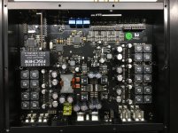
Atm, my mainboard is 120x120mm, with plenty of space over. I haven't used any I²S isolator-IC's, I have used the buffers posted in a schematic some posts back.
The main hurdle is still what pins to use from the "Core Boards", and routing it in Sigma Studio.
I will remove the +3.3Vdc reg on the Core Board and feed it from a very low noise LDO on the mainboard.
A clean power supply makes a world of difference, just look at the SlimDevices Transporter, with a few Ljung regulators it has better noise figures than the datasheet for the IC used.
I want SPDIF in (not toslink), I²S in and the same on the outputs, keeping all signal processing in the digital domain.
Lusya ADAU1452 - how to write to eeprom
- Hardware Configuration
- Right click on ADAU1452
- Self boot memory
- Write latest configuration through DSP
Did anyone figure out how to save to eeprom on the lusya adau1452? I can get it in temporary memory but not the eeprom memory. Even though I write to memory when i power cycle the board its back to the original config I am using I2S because i can't get my freedsp programmer working for SPI
Where is w7 on the board? Thank you
- Hardware Configuration
- Right click on ADAU1452
- Self boot memory
- Write latest configuration through DSP
Example USB SPDIF input 2/3 way XO
For those struggling to get their head around these boards I've attached a sample that works on the Lusya ADAU1452 dev board and codec.
I've enabled two I2S inputs to use with USB, plus spdif optical. Analogue inputs are turned off at present.
It uses an adc for volume control, the board in ADC2, it can easily be changed to ADC5, which then uses the end 3 pins on the connector near the onboard pot.
It switches between the XO2 and XO3 setups using MP7, the end switch.
Just add the filters and adjust XO as required.
It's not a perfect design, but it works.
I'm only using 1 USB at the minute, via Serial 2, but the config is on there for a second one on serial 3, but it's not tested.
In order to use serial 2 & 3 I've changed the settings to disable the relevant pins being used for LEDs
Attachments
Last edited:
For those struggling to get their head around these boards I've attached a sample that works on the Lusya ADAU1452 dev board and codec.
I've enabled two I2S inputs to use with USB, plus spdif optical. Analogue inputs are turned off at present.
It uses an adc for volume control, the board in ADC2, it can easily be changed to ADC5, which then uses the end 3 pins on the connector near the onboard pot.
It switches between the XO2 and XO3 setups using MP7, the end switch.
Just add the filters and adjust XO as required.
It's not a perfect design, but it works.
I'm only using 1 USB at the minute, via Serial 2, but the config is on there for a second one on serial 3, but it's not tested.
In order to use serial 2 & 3 I've changed the settings to disable the relevant pins being used for LEDs
Thanks 🙂
I'll have a look when I'm not with my daughter.
The guy helping me out with the theoretical stuff is about 2/3's through the ADAU1466 datasheet, and I sent him some other pdf's to read.
He's good at the the theory, the how and why stuff works.
My "expertise" is more in the practical stuff, ie doing a 4-layer PCB layout with pinsockets for the "Core Boards".
Fair warning, I tend to use 0402's, 0603's and only 0805 and bigger when I need to route traces between pads or when the value isn't available in high enough grade for mainly capacitors.
Last edited:
For those struggling to get their head around these boards I've attached a sample that works on the Lusya ADAU1452 dev board and codec.
I've enabled two I2S inputs to use with USB, plus spdif optical. Analogue inputs are turned off at present.
It uses an adc for volume control, the board in ADC2, it can easily be changed to ADC5, which then uses the end 3 pins on the connector near the onboard pot.
It switches between the XO2 and XO3 setups using MP7, the end switch.
Just add the filters and adjust XO as required.
It's not a perfect design, but it works.
I'm only using 1 USB at the minute, via Serial 2, but the config is on there for a second one on serial 3, but it's not tested.
In order to use serial 2 & 3 I've changed the settings to disable the relevant pins being used for LEDs
Thanks for your help!
Could you please send a picture of how you wired the USB input to I2S input (I assume you used Amanero or XMOS).
Also, how many I2S input are available in this board? I am using the same board with SPDIF input and analog output and using the ADC1 as volume control.
I am on my way (long way) to get HDMI --> 8 channel I2S and feed this DSP with I2S signal, using this board: RGB BT1120 BT656 Input to High Definition Multimedia Interface Output ADV7513 Development Board FPGA Display Solution Board|Cable Winder| - AliExpress
Thus it will be great to learn how to use I2S as input in the ADAU 1452.
Last edited:
I’m looking at these boards intently, is the usb input meant to be connected to a usb drive, does it connect with usb audio (allows the device connected (ipod, etc) to use it as an external dac) or does it enable connection to a PC to become a codec-like thing?
It is unclear.
I’ve just completed a project using I2s as an input on the adau 1701, there is a trick to it. I’ll post the link when i get to my other computer
It is unclear.
I’ve just completed a project using I2s as an input on the adau 1701, there is a trick to it. I’ll post the link when i get to my other computer
I have a 1452 implemented into a $$$ car amplifier/dsp. It has multiple spdif in and out, time alignment, etc... I wonder if it is possible to pull the program off of it? It has a custom laptop program, but i know that it programs the dsp on the fly from an atmega controller if you make changes. I think you can save configurations too.
Mayday: maybe some inspiration for you?
Unfortunately it is mounted in my car and I can’t get pics of it. But it is Helix P Six DSP mk2 HELIX P SIX DSP MK2 | Audiotec Fischer
Mayday: maybe some inspiration for you?
Unfortunately it is mounted in my car and I can’t get pics of it. But it is Helix P Six DSP mk2 HELIX P SIX DSP MK2 | Audiotec Fischer
Attachments
Thanks for your help!
Could you please send a picture of how you wired the USB input to I2S input (I assume you used Amanero or XMOS).
Also, how many I2S input are available in this board? I am using the same board with SPDIF input and analog output and using the ADC1 as volume control.
I am on my way (long way) to get HDMI --> 8 channel I2S and feed this DSP with I2S signal, using this board: RGB BT1120 BT656 Input to High Definition Multimedia Interface Output ADV7513 Development Board FPGA Display Solution Board|Cable Winder| - AliExpress
Thus it will be great to learn how to use I2S as input in the ADAU 1452.
The ADAU1452 has 4 serial inputs, each of which can do stereo I2S. (They can actually do more if you use TDM, but that's a whole other level)
The main problem is a clash between pins, some of the serial I/O pins are also GPIO (Multipurpose). You need to set up the hardware register to define what you're going to use them for.
See my other post for connections. I'm using an XMOS board
I’m looking at these boards intently, is the usb input meant to be connected to a usb drive, does it connect with usb audio (allows the device connected (ipod, etc) to use it as an external dac) or does it enable connection to a PC to become a codec-like thing?
It is unclear.
I’ve just completed a project using I2s as an input on the adau 1701, there is a trick to it. I’ll post the link when i get to my other computer
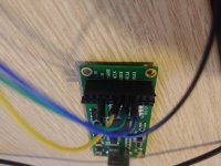
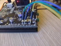
The onboard USB connector appears to be just power.
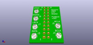
On the 30 pin connector
Pin 30 - GND
Pin 27 - LRCLK
Pin 23 - DATA
Pin 22 - BLCK
Excuse the obvious bodginess of this in the photos!
Needless to say, this is just testing
Any ideas on how to wire up two sets of I2S out?
Or atleast two SPDIF (coax) out?
I am trying to get the info off datasheets etc, but my chronic pain makes it hard to concentrate and remember what I've read.
EDIT:
I made a small, crude, layout of a pinheader to U.FL adapter.
Attachments

Last edited:
I have a 1452 implemented into a $$$ car amplifier/dsp. It has multiple spdif in and out, time alignment, etc... I wonder if it is possible to pull the program off of it? It has a custom laptop program, but i know that it programs the dsp on the fly from an atmega controller if you make changes. I think you can save configurations too.
Mayday: maybe some inspiration for you?
Unfortunately it is mounted in my car and I can’t get pics of it. But it is Helix P Six DSP mk2 HELIX P SIX DSP MK2 | Audiotec Fischer
From the parts I can see, that thing was not cheap.
Nicely done from a quick glance at it.
- Home
- Source & Line
- Digital Line Level
- low cost ADAU1452 China board...