You have to change the sample rate/clocks in several places in register control with ADAU1452, not just in the scheme tab.
Last edited:
Still have this start/stop issue.. I get 'USB device malfunctioned' from windows when it happens. Still happens when using a USB wall adapter. It seems to operate fine for a while turned on cold, then starts shutting down more often, perhaps the regulator circuit on the board is faulty
I'm doing some in depth investigation of using the ADAU1452/AD1938 board at 96kHz and 192kHz. And it's clear from what I found in the AD1938 programming and the board design that 96kHz and 192kHz are forcing the AD1938 to work out of specs. MCLK is supposed to be no more than 27MHz, but in this Lusya board it's 49MHz 😱.
Things are complicated by the fact that the AD1928 is programmed by an embedded processor with no way to change settings unless that processor is desoldered and the STM32 connected to the SPI pins
You can find more info on this thread I created in the AD support forum ADAU1452 & 192kHz TDM output to AD1938 - Q&A - Audio - EngineerZone
I'm taking more measurements for all jumpers configurations and will post them here soon. But bottom line is that using the Lusya board at 96kHz and 192kHz means that the AD1938 output will not be within specs, and probably have more audio artifacts than expected
Still have this start/stop issue.. I get 'USB device malfunctioned' from windows when it happens. Still happens when using a USB wall adapter. It seems to operate fine for a while turned on cold, then starts shutting down more often, perhaps the regulator circuit on the board is faulty
Well there is a poor, single AMS117-33 powering everything: ADAU1452, AD1938, STM32F103 and all other analog chips. The ADAU1452 alone can use more than 500mA, the AD1938 is ~200mA when fully powered, it's unclear how much the STM32 is using, let's say 50mA. Just just these 3 chips, we can use 750mA, out of an AMS117 that is rated for 800mA. Touch the AMS117 when running, and you'll see how hot it gets. Other chips get pretty hot, too, and there isn't a lot of air circulation or heat sinks on the board/copper planes
Pretty much everything on the Lusya board is operating outside of specs. It's very cheap and easily available, but not exactly a well designed board.
As a test, you can try disconnecting the AD1938 board and use only the ADAU1452. If yo don't have problems in that case, your root cause is the AMS117 being maxed out. If you still have problems, it's very likely not a power/heat issue
Last edited:
Hmm, AMS chip isn't particularly warm to the touch but I have discovered that I can still read signal levels and such from the 1452 so it looks like an issue with the codec board.
It certainly looks like a heat issue given the failure pattern.
I'd be really interested if anyone has setup a 1452 core board with separate DAC boards.
Edit: Yep... Blew some air in between the PCBs and we're stable again. Looks like the CODEC board s overheating
It certainly looks like a heat issue given the failure pattern.
I'd be really interested if anyone has setup a 1452 core board with separate DAC boards.
Edit: Yep... Blew some air in between the PCBs and we're stable again. Looks like the CODEC board s overheating
Alright, I have the Lusya 1452 pretty much all working now. Cheers to Vuki, Xplo5iv, mga2009 and robca for the help.
Summary:
Everything needed to get it to work:
This certainly has a lot of potential seeing as MiniDSP boards cost hundreds but I don't think I want to end up using the Lusya boards or similar. I'm thinking of getting a better core board and hooking it up via I2S to some higher quality DAC/ADC boards. If anyone has done a similar project then I would love to read about it.
Regards
Tadeusz
Summary:
- Codec board analog outputs are surprisingly good, about <0.1% THD and -100dB noise floor.
- Codec analog inputs are terrible so I'm using spdif input only.
- The outputs are extremely loud and the board occasionally produces tones when programming so pots must be used before an amplifier.
- Sure ICP3 programmer definitely works for programming both the 1452 and EProm
Everything needed to get it to work:
- Hook up SCL, SDA and GND from the ICP3 programmer.
- Removed jumper from Codec board for 48khz mode, 192khz causes it to overheat and shutdown.
- Config - USBi block, ADAU1452 connected to I2C 0x76, E2Prom connected to SPI 0x1.
- Setup the routing matrix for spdif input and used ASRC inputs in the schematic.
- SPDIF input worked when I set the SPDIF_RX registers to restart automatically on relock and audio word length to automatic.
- When EProm was wiped, had to power on the board with the jumper to turn off self-boot mode.
This certainly has a lot of potential seeing as MiniDSP boards cost hundreds but I don't think I want to end up using the Lusya boards or similar. I'm thinking of getting a better core board and hooking it up via I2S to some higher quality DAC/ADC boards. If anyone has done a similar project then I would love to read about it.
Regards
Tadeusz
Congratulations on having a working board! And, yes, when programming there is a real risk to get unwanted high volume sounds, so it's safer to have physical level limitation before an amplifier. Tweaking crossover parameters for a given configuration is pretty safe to do; it's the reprogramming of a configuration that cause the unwanted sounds.Codec analog inputs are terrible so I'm using spdif input only.
Keep in mind that the SPDIF on the ADAU1452 is limited to 96kHz according to Analog Devices. From my tests, it works at 192kHz using the RCA input, but I did not take any measurements to check audio quality. If you want to be on the safe side, use 96kHz max
Also, the optical receiver on the board only really works to 96kHz, being a 16Mbps part. For 192kHz optical a 25Mbps receiver is needed. But at 96kHz seems to work decently well even for longer optical runs with cables of questionable quality, so that's good
With the AD1938 board jumper open, the AD1938 works in 48kHz TDM mode, so you can output all 8 channels (4 stereo signals) on one serial output port from the ADAU1452
I2S input works really well. I'm using an Amanero Combo384 clone to send I2S data to the board and it works really well for all rates up to 192kHz
Tadeusz, I'm building one based off the 1467 for similar reasons - greater flexibility in input /output options. I'm not particularly interested in analogue inputs (I'll add one for aux use), the main thing I want is two xmos USB inputs and an sp/dif. I've got an i2s Bluetooth module I intend to add as well. Initially all 4 i2s DACs are pcm5102a, but that's mainly because they're dirt cheap for testing. It will have a very low noise psu, once I get round to building it.
It's feeding Linkwitz LXmini +2, using 3 of the DACs as active crossover, plus one aux out.
I'm still running on the 1452 until I get round to finishing it - it's not been without its challenges,and other distractions
It's feeding Linkwitz LXmini +2, using 3 of the DACs as active crossover, plus one aux out.
I'm still running on the 1452 until I get round to finishing it - it's not been without its challenges,and other distractions
Oh,and never change any filter modules when connected to anything that can't cope with a rail to rail square wave!
Ditto with touching anything i2s related
If you haven't realised already the correct output format for filters from REW is 'generic'
Ditto with touching anything i2s related
If you haven't realised already the correct output format for filters from REW is 'generic'
96kHz crossover
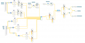
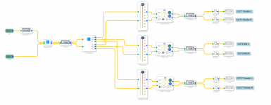
After having realized that the max core frequency for this board+codec is 96kHz, I started creating a skeleton project to be used in the future. And I thought that other people might benefit from it, since this is basically the highest quality we can get out of the board.
First of all, you need to set the SIP3 jumper on the AD1938 codec board to 96kHz, i.e. connect together pins 1 and 3. I'm using a thin solid wire, wrapped like the old wire wrap around the pins. Probably the safest option is to solder 1 and 3 together from the bottom, with a thin insulated wire.
That sets the board to use TDM for both ADCs and DACs. The project uses inputs 0-3, with 0-1 being L+R for input 1 on the codec board, 3 and 4 are L+R for input 2. The AD1938 is sending all 4 ADC channels in TDM format to serial port in 0.
For output, the 4 DACs in the AD1938 are fed from serial port out0, TDM format 8 channels. 0-1 are L+R for the jack marked out1, 2-3 for out2, 4-5 for out3 and finally 6-7 for out4.
In addition, I enabled the SPDIF input, thru an ASRC, and mapped to inputs 0-1 on the digital input block. Then 2 separate I2S inputs, which I mapped to serial in2 and serial in3. I don't use serial in1, because there are already enough inputs. But would be easy to add. All I2S inputs also go thru the ASRC, and are mapped to 2-3 for I2S 2 and 4-5 for I2S 3.
To connect an USB to I2S interface to, for example, I2S 3, connect the bclk output from the USB interface to BCLK_IN3, lrclk (or fsclk for the Amanero board) to LRCK_IN3 and finally the data line to SDATA_IN3. Also set the USB interface to 96kHz as well, even if the ASRC should be able to handle any other rate. A side effect of the board design, is that the LEDs will light with the I2S signals. I plan to address this in a future post (requires soldering on the board, though)
I put a mute control on each input, so that any unused input can be muted. I also put a DC blocker on every input because I noticed that without it, the level meters would otherwise see a signal on unused inputs. I don't think that a DC filter will cause problems, and it's an extra safety to protect the speakers connected to the board. And each input has its own input level control, to ensure all signals have the same level
Then there is an input selector that uses the button S3 to select the input. And the potentiometer on the board is used to control a master volume Since this is a learning project, I added a couple of read backs to see what values are selected by S3 and the potentiometer. I also added a ton of level indicators to be able to visually follow the signal, for the times I don't want to have any amplifier connected to the outputs.
For the outputs, I decided to have out4 as the "raw" output, no crossover. Each output can also be individually muted. I put the actual crossover on a separate tab, to keep the project visually clean. First there is a Parametric Equalizer to correct the signal, then a 3 way crossover. The outputs of the crossover feed into a separate level control for each of the 3 signals, then a delay to time align the speakers, and finally the individual outputs, each with a mute control
Since, once again, it's a learning tool for me, I added a stimulus and 4 separate probes to see how the signals change with the changing of parameters.
Lastly I tried to optimize the ADAU1452 for power consumption, more than anything to keep it cooler. In the Power Clocking tab of the ADAU1452 register controls, I disabled power for the unused serial ports (in and out). I also disabled SPDIF out, since I don't plan to use it. I'm not really sure how much it helps. but there's no harm in doing it and potentially an upside
I'm still trying to understand why I see some output with my oscilloscope on serial port 1 out, since it should all be off. But that causes no problems to the AD1938
Attachments
Last edited:
I ordered the board with coax SPDIF in and toslink in and out.
Along with the codec board. Just to have something to start with.
I believe the ADAU1452 board I ordered has a u-controller onboard.
Does this make any difference in how to program the board in Sigma Studio?
I'm also thinking about splitting the coax SPDIF in to two, having one go to dac, preamp, power amp and my Infinity's.
The other going to the ADAU1452 + Codec boards, from there to power amp and the 2x 15" dipole subwoofer.
Is this doable, can XMOS XU208 drive a Y-split cable?
SPDIF over coax has a 50 Ohm impedence, so it might or might not work depending on what kind of load the Tx portion sees. For low enough frequencies (96KHz and below), it should work if the wires are short and the splitter has a "clean" signal
Keep in mind, though, that the ADAU1452 introduces a signal delay. So if you plan to have, say, the main stereo channels from the DAC to the amplifier toi , then the same DAC to the ADAU1452 to the subwoofer, your sound will be mangled pretty badly
Also, the amplifier itself will add an unknown delay, given that it will also have to do some sort of D to A conversion (SPDIF to analog at a minimum, possibly have its own DSP for signal shaping)
The only "good" way to do an active multichannel setup with a DSP like the ADAU1452, is to have the signal into the ADAU1452, processed, then multiple analog outs, each feeding into a purely analog amplifier block (or a multichannel amplifier with no processing)
A DSP is not an analog filter that can be added at any point in the signal chain.
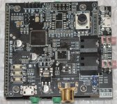
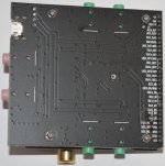
The board(s) I bought.
I wound up getting the ADAU1452/STM32F103 + AD1938 Combo.
The reason being that I figured it would be easier to get started with.
There are a few questions though.
1. Interface with SigmaStudio? I have a FreeUSBi+EZ-USB V.0.2, but I'm not sure if it works with this board
2. I've (years ago) managed to get crossover and dipole compensation done in SigmaStudio for ADAU1701(the ADAU1452 is a different beast all together), has anyone here done this on this board? I want to set up a 2.1 system with my Infinity speakers cut off at 80-100hz, and let two Dayton 15" IB woofers in parallel handle 80-100hz down to about 25hz.
3. I have a measuring mic built according to Linkwitz site, including a OPA2134 mic amp. But I am thinking of getting a UMIK-1.
The positioning of my speakers is far from ideal and I'm sure SQ will be significantly improved with room correction via REW and SigmaStudio.
I have never done that however, and have no clue how to implement the output from REW in SigmaStudio.
Thus far, I've only taken the DSP/Codec out of the packaging to take the pics attached.
I just now noticed that the STM32F103 seem to have been removed. I don't know if that is the case with all these boards?
Attachments

Last edited:
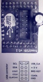
I've read of multiple ways to connect to the various boards discussed in this thread, I am wondering which is the correct way to connect the freeUSBi to the ADAU1452 board (the version without the STM32F103 microcontroller)? I have pictures of my board attached in the post above.
In essence; what pins from the freeUSBi to connect to what pins on the DSP board?
In essence; what pins from the freeUSBi to connect to what pins on the DSP board?
Attachments
Different boards have different resistor configurations (you can see it from the schematic), so it really depends on your board.
The best way to find if you need SPI or I2C (the only 2 ways to connect), is to follow the ADAU board USBi connector with a multimeter in low ohm mode (or, if it has the function, the continuity beeper). Find which USBi pins are connected to the I2C or SPI pins on the ADAU chip, and you'll know if I2C or SPI work
Alternatively, just try first one (SPI or I2C) then the other. There's no risk of damage as long as you use a working USBi adapter
SDA SCL GRND
With only that 3 pings I program my ADAU1452 with my USBi
As I've read in this thread, i2c for the ADAU1452 and spi for eeprom (via DSP)?
I only use I2C without a problem.
Ok.
I suppose it'll be a little trial and error to see what works on my board. Can't really brick it unless I really screw up I guess. In that case I have two working ADAU1701 boards to fall back on.
I still have a lot to learn about how to configure the setup in SigmaStudio and, at some point, using REW to measure the room, make corrections and then implementing that in SigmaStudio.
- Home
- Source & Line
- Digital Line Level
- low cost ADAU1452 China board...