Thanks for your reply!
1-. OK. The power used by this board (according to cipdip.ru) is 5V, that's why I tried 5V, will try again with 3.3v using the same 10kOhm res.
2-. No, not trying to save between powerups, but thanks for clarifying me that the AD1938 does not have memory. With the codec always powered up, I tried to write some configurations write them thru register control, and then hoping that when when pushing "get current settings it all will stay like that.
The Lusya DSP has a uC, ok... so I need to include in my SS schematic a "Master Control Port" (Startup Boot > Master Control Por IO) with the correct sequence file for my CODEC?
Don't know which pins I need to connect thou...
3-. OK. But the uC is in the DSP board or on the CODEC board? My Lusya 1452 has a uC in the DSP board.
Also, I don't see any jumpers on my Lusya DSP, and also can't see a "Master Control Port" in the default "schematic". I only have one jumper in the Lusya CODEC beside a tiny uC. I assume this is it?
The chipdip.ru CODEC boards do not have uC onboard.
4-. You are right, lets forget about daisy chain, and only have 1 codec board (the ones from chipdip.ru, the Lusya Codec board works OK) up and running with my DSP.
I will revise all of your post if I am missing something.
Attachments
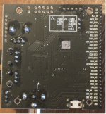
1) yes, the board is powered by 5V. And the board has a 3.3V converter on it for the AD1938. The AD1938 is only a 3.3V chip. Never use 5V on any AD1938 pin. Hopefully you have not damaged it yet (but I would say it's suspect, until you can prove it works... )
The Lusya ADAU1452 board has a STM32 processor on it. To program that one you need the proper STM32 development environment (e.g. STM32Cube IDE STM32CubeIDE - Integrated Development Environment for STM32 - STMicroelectronics) and an ST Link to upload programs to hat processor. It's an entirely different beast and you will need to become familiar with STM32 development tools. SigmaStudio has nothing to do with that STM32. For most people the STM32 on the ADAU1452 board is useless and some similar boards do not include it. For the people who know STM32 programming, that processor can be used to dynamically change the ADAU1452 settings and significantly expand I/O possibilities
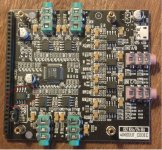
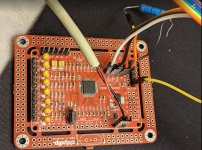
The Lusya AD1938 board also has a small processor, the one circled in red in your third picture. The jumper right below it is used to change settings. That small processor is not programmable: there is already code on the processor to read the status of the jumper and program the right register at power up. In my post I list all the various settings entered by that processor in the AD1938
By using the chipdip.ru AD1938 board, you potentially have a lot more flexibility, but also a much harder learning curve. You also need the schematic for that board to understand how it's configured (standalone vs programmable), if it's using I2C or SPI, and in that case which address. You seem to use SPI 01 and SPI 02 in your SigmaStudio project, but are you even sure that the boards are set up for SPI and the right address?
I think you should really spend some time reading the AD1938 datasheet at least twice (some things only make sense when read the second time) and understand how to program that board. I don't mean to sound rude, but it looks like you started connecting things semi randomly and adding semi-random components to a SigmaStudio project 🙂
And I would start very simple: connect only one AD1938 to USBi (I2C or SPI, as needed), ensure it's set up for programmable mode, understand what address it's using, then create a SigmaStudio project with only the USBi and AD1938 (using the I2C or SPI address you got from the previous step), read all the registers, print or save that data to a file, then write some different values into the registers, read it back and ensure that you can read the values you entered. Power off the AD1938, read back the register to ensure you get the default values. If you can do all that, then everything else follows logically from there. Next step would be to set up the second AD1938 board with a different address, and ensure you can read and write that one, too. Then try both AD1938 connected, and ensure you can still read and write. Finally add the ADAU1452, program one AD1938 like the one on the Lusya board, and use an example project for the ADAU1452 to ensure you can send and receive data from one AD1938. After all that, you can try ot figure out daisy chaining (which from everything I read, it's really complicated, much more so than anything else I discuss here)
The Lusya ADAU1452 board has a STM32 processor on it. To program that one you need the proper STM32 development environment (e.g. STM32Cube IDE STM32CubeIDE - Integrated Development Environment for STM32 - STMicroelectronics) and an ST Link to upload programs to hat processor. It's an entirely different beast and you will need to become familiar with STM32 development tools. SigmaStudio has nothing to do with that STM32. For most people the STM32 on the ADAU1452 board is useless and some similar boards do not include it. For the people who know STM32 programming, that processor can be used to dynamically change the ADAU1452 settings and significantly expand I/O possibilities
The Lusya AD1938 board also has a small processor, the one circled in red in your third picture. The jumper right below it is used to change settings. That small processor is not programmable: there is already code on the processor to read the status of the jumper and program the right register at power up. In my post I list all the various settings entered by that processor in the AD1938
By using the chipdip.ru AD1938 board, you potentially have a lot more flexibility, but also a much harder learning curve. You also need the schematic for that board to understand how it's configured (standalone vs programmable), if it's using I2C or SPI, and in that case which address. You seem to use SPI 01 and SPI 02 in your SigmaStudio project, but are you even sure that the boards are set up for SPI and the right address?
I think you should really spend some time reading the AD1938 datasheet at least twice (some things only make sense when read the second time) and understand how to program that board. I don't mean to sound rude, but it looks like you started connecting things semi randomly and adding semi-random components to a SigmaStudio project 🙂
And I would start very simple: connect only one AD1938 to USBi (I2C or SPI, as needed), ensure it's set up for programmable mode, understand what address it's using, then create a SigmaStudio project with only the USBi and AD1938 (using the I2C or SPI address you got from the previous step), read all the registers, print or save that data to a file, then write some different values into the registers, read it back and ensure that you can read the values you entered. Power off the AD1938, read back the register to ensure you get the default values. If you can do all that, then everything else follows logically from there. Next step would be to set up the second AD1938 board with a different address, and ensure you can read and write that one, too. Then try both AD1938 connected, and ensure you can still read and write. Finally add the ADAU1452, program one AD1938 like the one on the Lusya board, and use an example project for the ADAU1452 to ensure you can send and receive data from one AD1938. After all that, you can try ot figure out daisy chaining (which from everything I read, it's really complicated, much more so than anything else I discuss here)
Last edited:
1-. OK. I hope I didn't damage it. I have another one to test.
Also, Can I use a resistor of different value? Maybe 22kOhm?
And... I forget about STM32 then... way over my head.
2-. I assume chipdip.ru AD1938 use SPI as that's what is said in the schematic diagram: AD1938 CODEC V2, Преобразователь: I2S - Аудио - I2S. 8 линейных выходов, 4 дифференциальных входа, 192kHz/24bit, Электронные войска | купить в розницу и оптом
I am not sure on the address.
3-. I will read again the AD1938 datasheet... aaannnd... you are probably right about connecting things semi randomly and adding semi-random components to a SigmaStudio project.. but that's the way to learn your hobby.
4-. I already tried starting simple... and connect only one AD1938 to USBi thru SPI.... but it's not pgoramable...
Should I try all the different addresses in SigmaStudio to see If it makes a difference?
If I am luck and I manage to program it with USBi... what are my alternatives for programming on every day use? Arduino?
I really thought this was much easier, like ADAU1701 and I2S codecs... but it isn't.
Cheers and thanks for your help
Allow me to step on my soapboax for a moment and point out that the way we learn in this hobby is by reading existing documentation 🙂 The ADAU1452 and AD1938 are exceptionally complex devices with a lot of configurabiliy and functionality. Just trying to get something to work by trying various combinations is simply not possible. And, yes, this is at least an order of magnitude more complex than the ADAU1702. Especially when you use an AD1938 that needs independent configuration unlike the Lusya one.3-. I will read again the AD1938 datasheet... aaannnd... you are probably right about connecting things semi randomly and adding semi-random components to a SigmaStudio project.. but that's the way to learn your hobby.
Let's see how we should break this down. Let's start by looking at the schematic and figuring out how the board is configured.
According to the AD1938 datasheet, "It is recommended to use a weak pull-up resistor on CLATCH in applications that have a microcontroller". On the schematic https://static.chipdip.ru/lib/840/DOC005840357.pdf there is no pull op on pin 27 (CLATCH). So you need a "weak pullup" (anything >20kOhm and less than, say, 100kOhm) between +3.3V and pin 27 (also pin 5 on J9). So, yes, 22kOhm works well
Speaking of J9, I assume it's there to allow you to use the SS, MISO, MOSI and CLK signals from the edge pads. You can connect the resistor to pin 5 on J9, and use pins 2,3,4 and 5 on J9 to connect your USBi. Or put the jumpers on J9 and use the edge pads. Either way works
As for SigmaStudio, it uses a rather weird way to address chips via SPI, using the Latch1-4 on USBi to decide what AD1938 it's talking to. This thread has a bitmap that explains how to connect multiple AD1938 to USBi and what to use in SigmaStudio to select the right AD1938 Two AD1938 in daisy chain with ADAU1452 - Q&A - SigmaDSP Processors and SigmaStudio Development Tool - EngineerZone
Once you can read and write a single AD1938 with the USBi, you can then add the rest using different LATCH on USBi and CS on the AD1938. Then figure out how to program each AD1938 to do what you want. Once you have the raw data to write in each registry of the AD1938, you can then use any processor (yes, including Arduino) to properly program the AD1938. You will need an SPI library, proper connections and ensure that you send the SPI data according to the datasheet (it's under SERIAL CONTROL PORT). Since you won't have the benefit of the USBi in that case, it might take some time to ensure you can read and write the correct data. The easiest way would be to store the binary data inside the code itself (hardcoded), already formatted so that it can be sent using simple sequential SPI writes
Sorry I can't help more, but I don't have an AD1938 board that can easily be programmed with an USBi, so I can't give you the exact steps. It would require desoldering the processor from my Lusya AD1938 board, and at this time something I plan to do (since the preprogrammed data works well enough for me, now that I decoded what it does). Unless you want to send one of your boards to Seattle 😀
Technically, the STM32 on the Lusya ADAU1452 board can be programmed with the Arduino framework (since ST Electronics supports the Arduino libraries). But unless you have already used Arduino on STM32, it's probably a lot easier to use a 3.3V Arduino board (i.e. do not use a 5V Arduino, unless you want to deal with level shifters and introduce even more complexity)
If I ever find the time, I might write a simple example on how to use the STM32 on the Lusya board to connect to I2C and SPI devices with the Arduino framework. It would require an ST Link (which is only a few $ on eBay) and some soldering, at least for the Lusya AD1938 board which doesn't expose the SPI pins (since it's programmed by the onboard small processor). But it's very low on my priority list and the list is very, very long and keeps growing 😉
Thanks for your help.
I managed to write and read the register controls of my AD1938 codec using my USBi
Of course, once powered down, it al goes to default, which is as shown in in attached register control.
So, now I need a uC so I can load the proper configuration each time it boots, right? Well, this is uncharted territory for me, so I will start looking up.
OTOH, I think in this thread:
Controlling AD1939 via master control port ADAU1452 - Q&A - SigmaDSP Processors and SigmaStudio Development Tool - EngineerZone
It says the ADAU1452 can load an config fie to the codec thru the master control port. This is available only in the EVAL-ADAU1452REVBZ and not in the Lusya ADAU1452?
More info here: Master Control Port Boot time I/O (ADAU145x) [Analog Devices Wiki]
Attachments


Last edited:
Good progress on the USBi
And good find on the master control port. That seems to be ideal for your case. I's something I never saw before (good, today I learned something new 🙂)
It should work on the Lusya board as well, the only challenge might be to find enough free I/O pins to drive both AD1938. Most I/O pins are already used, so you might need to cut traces to the LEDs to use those I/O pins
Another thing you need to pay attention to is that the AD1938 board you have uses an ADM6316 as a supervisory/reset circuit, and you need to make sure that the AD1938 is fully booted before configuring it (the processor on the Lusya AD1938 has a small delay before setting the registers, and also sends the data twice). If you see that not always the AD1938 is properly configured, you can also send the configuration data twice: if it works both times, no problems, but if the first time it fails, the second time will work for sure
If you ran into problems where nothing works even if everything seems to be ok, you might need to use a logic analyzer to inspect the signals, the timing and that data. With a logic analyzer you can see all the SPI packets and the content of each (it's what I did to understand how the Lusya AD1938 board works). The good news is that the speeds are very low, so even a very cheap 24MHz/8 channel Saleae clone will work well. Those cost less than $10, and learning how to use one is a great investment in this hobby. Just search for "24mhz logic analyzer" on eBay or Aliexpress (no quotes)
Hope you can make i work. Otherwise a separate processor will work for sure
Thanks for your reply.
Yes, I will try to find some MP pins so I can test them with 1 codec.
I will report if that work, and yes... I will probably get a Logic Analyzer as you said. Very useful tool.
Also, I would like to ask you something... in AD's forumd, DaveThib mentioned that hen my codec PCB will probably have some issues with the PLL locking and noise floor will not be good, as the locations of the bypass caps with relation to the chip is not good, and the PLL loop filter needs to return to the power pin right next to the LF pin. He says in the ADAU1452 datasheet there is a layout example on how the bypass caps should be connected.
If I understand correctly, this is NOT something I can fix, correct? The PCB needs a redesign to accomplish this. correct?
Cheers.
Well, the best person to answer would be the chipdip.ru designer. In general, reworking an existing PCB is hard-to-impossible. Adding a decoupling capacitor near the right pins might be achieved with a thru-the-hole capacitor soldered directly across pins, but it's always hard/difficult to do it properly and not mess up things
It's also possible that the AD engineers are being very conservative and go by the specs, while the chipdip.ru designer might have tested various positioning options and measured no meaningful difference. Or it can be something that the designer was not even aware of. Hard to say
Most cheap commercial AD1938 boards are likely to have poor noise characteristics, anyway. Definitely the Lusya AD1938 board is not that great, but good enough for tests and experiments. Noise will also depend on the power supply, wiring layout, enclosure, etc. So it's something that you will need to measure on your final design (that requires an oscilloscope, though)
I would highly recommend asking who sold you the boards and see what what say
Thanks for your reply.
Sadly the DSP is designed by chipdip.ru and I really don't speak russian, so no chance to contact them; i also think they do not provide support... IDK.
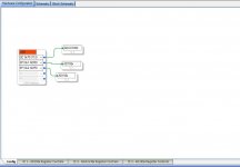
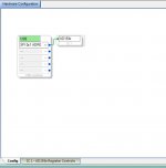
I managed to get the codec sequence file using Master Control Port in my SS schematic and properly downloaded to the DSP.
I am using MP13 for control port.
Now, I understand this is the basics, but still I don't get it.
So, my MP13 is my control port, so I have to connect it to my CODEC pcb... but to which pin? Any other pin (besides the control port) is required for this programming?
My understanding (informed guess), as I am using SPI on my master control, is MP13 goes to CODEC MISO, DSP CS goes to CODEC SS, and DSP SCL/CLK goes to CODEC SCL
Sadly the DSP is designed by chipdip.ru and I really don't speak russian, so no chance to contact them; i also think they do not provide support... IDK.
I managed to get the codec sequence file using Master Control Port in my SS schematic and properly downloaded to the DSP.
I am using MP13 for control port.
Now, I understand this is the basics, but still I don't get it.
So, my MP13 is my control port, so I have to connect it to my CODEC pcb... but to which pin? Any other pin (besides the control port) is required for this programming?
My understanding (informed guess), as I am using SPI on my master control, is MP13 goes to CODEC MISO, DSP CS goes to CODEC SS, and DSP SCL/CLK goes to CODEC SCL
Attachments
I have absolutely no experience at all in this, but reading the links you provided, the MP pin you select acts as a Chip Select for the SPI, which in the case of the AD1938 is called CLATCH and active low.So MP13 should be connected to CLATCH on the AD1938, if I'm reading his right You can have multiple SPI devices on the same bus, all sharing MISO, MOSI and CLK. In order to write to a specific device on that bus, you select the device with CS (CLATCH in the AD1938), then send the proper SPI signals. All the other devices are not selected, and do not receive data, even if there is a signal on the device pins. To use an analogy, it's like a teacher calling out a student name before asking a question: every student in class hears, but know that the question is not for them.
The CLK signal is pretty clear, and works the same if the USBi or ADAU1452 are controlling the AD1938. What I would not be sure about is the MISO and MOSI signals. In normal SPI devices, when a device is acting as a master (e.g. the USBi), MISO is Master In, Signal Out and MOSI is Master Out, Signal In. When the same device acts as a slave, MISO and MOSI are swapped. So I would not know if you need to swap MISO and MOSI or not
This is the perfect case for using a logic analyzer, btw. Connect the logic analyzer in parallel to your USBi pins (4 pins, using 4 of the logic analyzer 8 inputs), program the AD1938 with USBi while you capture the SPI signal (using the SPI decoder), and store. Then connect your logic analyzer to the 4 pins from the ADAU1452 and capture the data when the codec sequence file is generated at boot time. By looking at he USBi signal and comparing it to the ADAU1452, it will be immediately clear which pin does what and what you need to connect
Awesome!
Thanks for your reply!
I will purchase the logic analyzer now, and wait a few weeks to arrive.
Cheers
Thanks for your reply!
I will purchase the logic analyzer now, and wait a few weeks to arrive.
Cheers
I think I need some help!
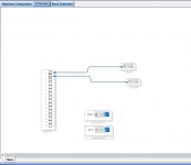
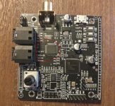
I've got the ADAU1452 board shown. (As you can see I've broken out all the MP/GPIO pins and wired MP13 directly to the LED).

I can program the DSP it just fine from SigmaStudio over the I2C bus using an FTDI and the drivers that make it pretend to be a USBi. The program runs perfectly.
I can not manage to get it to save it on EEPROM (then self-boot).
Every time I self-boot it seems to load a default program.
I believe this board has an I2C EEPROM (ATMLH542ECL can't find datasheet), because according to the schematic (attached) it has the resistors for that arrangement.
That said, I've tried both I2C and SPI when selecting 'Write latest compilation through DSP'. I've tried it with and without the self-boot jumper.
Inspecting the EEPROM IC pins are as follows - A0 HIGH, A1 LOW, A2 LOW, WP LOW, SCL and SDA pulled HIGH.
I even tried installing a different I2C EEPROM and it also did not write.
I tried pulling A0 low. Still no luck. I do note the ADAU1452 datasheet says it expects EEPROM at 0x50 (I think this is a 7-bit hex string, so 0xA0 in 8-bit which SigmaStudio shows, dunno why they can't just stick to one!).
I've got the ADAU1452 board shown. (As you can see I've broken out all the MP/GPIO pins and wired MP13 directly to the LED).
I can program the DSP it just fine from SigmaStudio over the I2C bus using an FTDI and the drivers that make it pretend to be a USBi. The program runs perfectly.
I can not manage to get it to save it on EEPROM (then self-boot).
Every time I self-boot it seems to load a default program.
I believe this board has an I2C EEPROM (ATMLH542ECL can't find datasheet), because according to the schematic (attached) it has the resistors for that arrangement.
That said, I've tried both I2C and SPI when selecting 'Write latest compilation through DSP'. I've tried it with and without the self-boot jumper.
Inspecting the EEPROM IC pins are as follows - A0 HIGH, A1 LOW, A2 LOW, WP LOW, SCL and SDA pulled HIGH.
I even tried installing a different I2C EEPROM and it also did not write.
I tried pulling A0 low. Still no luck. I do note the ADAU1452 datasheet says it expects EEPROM at 0x50 (I think this is a 7-bit hex string, so 0xA0 in 8-bit which SigmaStudio shows, dunno why they can't just stick to one!).
Attachments
Can you give more information about how you tried to program the EEPROM?
IIRC you need to do it manually on the "harware" tab by right-clicking the DSP. It's not written automatically when writing from SS.
IIRC you need to do it manually on the "harware" tab by right-clicking the DSP. It's not written automatically when writing from SS.
I do note the ADAU1452 datasheet says it expects EEPROM at 0x50 (I think this is a 7-bit hex string, so 0xA0 in 8-bit which SigmaStudio shows, dunno why they can't just stick to one!).
I don't have specific suggestions on how to solve your problem, sorry. But I can help explain the 7/8 bit addresses. It's part of the I2C standard, with bit 7 being the read/write flag. Here's a better explanation
7-bit I2C Slave Address
A 7-bit I2C address includes a 7-bit slave address in the first 7 bits of a byte. The eighth bit (the bit in the Least Significant Bit position) is the read/write flag. A 0 in the eighth bit indicates a write and a 1 in the eighth bit signifies a read
So, depending on which way a company thinks about I2C and bit 7, you can find two addresses for the same chipA 7-bit I2C address includes a 7-bit slave address in the first 7 bits of a byte. The eighth bit (the bit in the Least Significant Bit position) is the read/write flag. A 0 in the eighth bit indicates a write and a 1 in the eighth bit signifies a read
Have you tried the instructions in post 153 of this thread?
Although it says 1467, I've also got a 1452 and it works fine with the Sure programmer
Connection to eeprom is SPI via DSP
Although it says 1467, I've also got a 1452 and it works fine with the Sure programmer
Connection to eeprom is SPI via DSP
Yes I did see your post 153, thanks.
I tried to write the EEPROM by first loading the program to DSP 'Varify, Compile, Upload'. That part works well. Then in the hardware tab I right-click adau1452 > selft boot memory > write latest compilation through DSP.
I tried both SPI and I2C modes and I tried with the self-doubt jumper in both positions (when first booting and when writing eeprom).
Nothing sticks.
I do believe it is loading from EEPROM because with self-boot enabled it lights the LED brightly. With self-boot disabled the LED only glows very faint. I just cant make it save MY data.
It's as though the EEPROM is in write protect mode.
Maybe it's a poop board or eeprom has a fuse? If I buy a different board which one is recommended? The Media Works core DSP looks common. FreeDSP Aurora looks nice too but I don't know where to buy??
Code:
Yes I did see your post 153, thanks.
I tried to write the EEPROM by first loading the program to DSP 'Varify, Compile, Upload'. That part works well. Then in the hardware tab I right-click adau1452 > selft boot memory > write latest compilation through DSP.
I tried both SPI and I2C modes and I tried with the self-doubt jumper in both positions (when first booting and when writing eeprom).
Nothing sticks.
I do believe it is loading from EEPROM because with self-boot enabled it lights the LED brightly. With self-boot disabled the LED only glows very faint. I just cant make it save MY data.
It's as though the EEPROM is in write protect mode.
Maybe it's a poop board or eeprom has a fuse? If I buy a different board which one is recommended? The Media Works core DSP looks common. FreeDSP Aurora looks nice too but I don't know where to buy??
There might be a write protect pin (jumper) that prevents overwriting the Flash ROM by mistake. Are you sure that the file you enclosed is the schematic for your board? It's the same schematic as the "black board" that looks quite different
It's almost impossible that the board is good, self boots from Flash, but somehow you cannot write to Flash. There's no point in buying another board, yours is almost surely good. You just have to find the right incantations to make it work. I previously suggested to use a logic analyzer, and in this case you could figure out what's wrong in a few minutes, with a logic analyzer
Possibly a silly question, but did you restart the board after moving the jumper? Then move it back and restart after reprogramming.
As well as the Lusya 1452 I have a MediaWorks 1467. The latter is much better, but only has digital i/o so needs DACs etc.
As well as the Lusya 1452 I have a MediaWorks 1467. The latter is much better, but only has digital i/o so needs DACs etc.
Member
Joined 2018
FT232H Driver for SigmaStudio
Hello Tenson-San,
I would like to know more details about this driver. Because my Un-Signed FreeUSBi driver fails with some Windows10 machines...
CyberPit
I think I need some help!
I can program the DSP it just fine from SigmaStudio over the I2C bus using an FTDI and the drivers that make it pretend to be a USBi. The program runs perfectly.
Hello Tenson-San,
I would like to know more details about this driver. Because my Un-Signed FreeUSBi driver fails with some Windows10 machines...
CyberPit
I found it very difficult to install it. I wrote the method to successfully install the drivers on Win10 here - STEP 5: Mr. Speaker - 3D Printed DSP Portable Speaker : 9 Steps (with Pictures) - Instructables
- Home
- Source & Line
- Digital Line Level
- low cost ADAU1452 China board...