Any ideas on how to wire up two sets of I2S out?
Or atleast two SPDIF (coax) out?
I am trying to get the info off datasheets etc, but my chronic pain makes it hard to concentrate and remember what I've read.
EDIT:
I made a small, crude, layout of a pinheader to U.FL adapter.
I've not done it yet, but should be fairly straightforward to use any of the 4 serial out ports for I2S.
Note that on the Lusya board they're already all used by the AD1938 codec
There's only 1 SPDIF output, pin 5
My 'real' build is going to use the ADAU1467 core board, as the Lusya 1452 board has too many of its GPIO connected to 'stuff' for my application. The 1467 board wasn't that much more than a 1452, so I thought I'd get it.
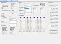
Could you send some captures of your "Hardware Register" in SigmaStudio to see how is it configured to accept USB to I2S at SDATA2?
Thanks
Thanks
From the parts I can see, that thing was not cheap.
Nicely done from a quick glance at it.
Yea, each amp was in the $2k range. I wasn't into the DIY scene when I bought them, but it shows that the potential for these parts is huge with the right "care and feeding" 🙂
I've not done it yet, but should be fairly straightforward to use any of the 4 serial out ports for I2S.
Note that on the Lusya board they're already all used by the AD1938 codec
There's only 1 SPDIF output, pin 5
My 'real' build is going to use the ADAU1467 core board, as the Lusya 1452 board has too many of its GPIO connected to 'stuff' for my application. The 1467 board wasn't that much more than a 1452, so I thought I'd get it.
I'll most likely use the ADAU1466 core board, as you say, it's not much more than the 1452 version.
I have two FreeUSBi to program with(had to order more than one pcb and populated two of them), it works as I've tested it on the FreeDSP Classic.
From what I've read so far, you have to send the SPDIF (and I2S?) to the ASRC (ASRC routing tab in SigmaStudio) first as much of what I listen to is RBCD and the DSP wants 18bit 192Khz IIRC. I may dedicate one of my laptops to Daphile and replace the RPi 3B+ that's now running OSMC(my daughter has a lot of movies I've backed up to a FreeNAS server, that's why I want the video part as well), using the RPi 3B+ for video only.
If I only understood SigmaStudio better, it would making a "mother board" for ADAU1466/1452(same pinout from what I gather) a whole lot easier.
Still haven't decided if I should make the MB barebones with terminals for external vregs, or if I should put 3-pin holes for flexibilty(I have both LT3042 and TPS7Axxxx with 78xx/79xx pinout).
I'll have to write more later, I just ran out of time lol
Hello Mayday-San,
Maybe you can see some ideas in my board design...
(Sorry! written in Japanese)
DIY DSP PRE-AMP PROJECT PAGE
(Machine Translation)
Google Translate
CyberPit
Since I haven't had the time to make much progress on the mainboard for the Core Boards, I was wondering if you had a BOM for your board?
Best regards
Member
Joined 2018
Hello Mayday-San,
DIY DSP PRE-AMP PROJECT PAGE
Kind Regards,
CyberPit
Here you 'll find BOM-LIST link in this page, at the Board Design Files Part...Since I haven't had the time to make much progress on the mainboard for the Core Boards, I was wondering if you had a BOM for your board?
DIY DSP PRE-AMP PROJECT PAGE
Kind Regards,
CyberPit
Hello Mayday-San,
Here you 'll find BOM-LIST link in this page, at the Board Design Files Part...
DIY DSP PRE-AMP PROJECT PAGE
Kind Regards,
CyberPit
Thank you very much CyberPit-San.
Kind Regards,
Mayday
Hi CyberPit-SanHello Mayday-San,
Here you 'll find BOM-LIST link in this page, at the Board Design Files Part...
DIY DSP PRE-AMP PROJECT PAGE
Kind Regards,
CyberPit
I assume it would be possible to use RCA or BNC connectors for SPDIF in and out if you have external boards with Murata DA101C or similar, wiring RX&GND and TX&GND from(unpopulated) optical connectors?
I may be wrong, it was just a thought as I prefer those over optical connectors.
Kind Regards,
Mayday
Member
Joined 2018
Hi Mayday-San,
interfacing between I2S and S/PDIF requires Bi-phase mark modulation and demodulation devices such as called as DIT/DIR. If you want to add Coax S/PDIF terminal, we need additional pulse-transformers, RX-Amp(Comparator) and 75ohms Coax driver Circuity.
In today, there are various sampling rate sources should be acceptable. This means that the SRC(Sampling Rate Converter) also needed for RX side. 😱
To making a sense, It's better to change DSP device, such as ADAU1452 or ADAU1466 which has integrated DIR, DIT and ASRCs. it's an attractive feature but not easy as cake... 😀
CyberPit
I assume it would be possible to use RCA or BNC connectors for SPDIF in and out if you have external boards with Murata DA101C or similar, wiring RX&GND and TX&GND from(unpopulated) optical connectors?
interfacing between I2S and S/PDIF requires Bi-phase mark modulation and demodulation devices such as called as DIT/DIR. If you want to add Coax S/PDIF terminal, we need additional pulse-transformers, RX-Amp(Comparator) and 75ohms Coax driver Circuity.
In today, there are various sampling rate sources should be acceptable. This means that the SRC(Sampling Rate Converter) also needed for RX side. 😱
To making a sense, It's better to change DSP device, such as ADAU1452 or ADAU1466 which has integrated DIR, DIT and ASRCs. it's an attractive feature but not easy as cake... 😀
CyberPit
Last edited:
Hi Mayday-San,
interfacing between I2S and S/PDIF requires Bi-phase mark modulation and demodulation devices such as called as DIT/DIR. If you want to add Coax S/PDIF terminal, we need additional pulse-transformers, RX-Amp(Comparator) and 75ohms Coax driver Circuity.
In today, there are various sampling rate sources should be acceptable. This means that the SRC(Sampling Rate Converter) also needed for RX side. 😱
To making a sense, It's better to change DSP device, such as ADAU1452 or ADAU1466 which has integrated DIR, DIT and ASRCs. it's an attractive feature but not easy as cake... 😀
CyberPit
Hi CyberPit-San,
So, as I suspected, not as easily done as I was hoping.
Still, I could get by with the I²S outputs and USB via Amanero or XMOS XU208 (my board seem to have the same pinout as the Amanero).
Mayday
Does anyone tried to daisy chain the AD1938 CODEC that comes with the ADAU1452 to get 8 channel input and 16 channel output?
It requieres TDM connection between DSP and CODEC
The register controls of the AD1938 contemplate an specific option for the daisy chain connection, but I could not find any option in the DSP's register control to enable TDM comunication in the Serial Output Ports, only can select the TDM mode, which in this case should be 8 channels and only use two serial outputs.
Attachments
UPDATE:
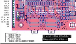
Here is a diagram of the CODEC that shows the required pinout for TDM.
Google Translate:
I2S output uses "SDATA out" 0/1/2/3 (4 ports)
TDM output uses "SDATA out" 0 (single port)
Here is a diagram of the CODEC that shows the required pinout for TDM.
Google Translate:
I2S output uses "SDATA out" 0/1/2/3 (4 ports)
TDM output uses "SDATA out" 0 (single port)
Attachments
Last edited:
As it's taken me some effort to get this to work, thought I'd write it here in case it's helpful.
I'm now using a MediaWorks ADAU1467 core board from AliExpress, and a Sure programmer.
I'm using I2C for programming, with SCL, SDA, GND & 5V connected from the programmer to the board. No modifications to either. I2C Address is 0x76.
E2Prom is configured in SigmaStudio, left with default settings. SPI 0x1 ADR0
Connect it all up, you may need extra board power, but if no peripherals I found I could program ok with just the programmer powering things.
Turn self boot switch to off.
Press reset on programmer
Press reset on board
Press reset on programmer.
You can now link-compile-download without problem.
To program the E2Prom do as above, then turn self boot switch on. (important!)
Hardware Configuration - Config. Right click on ADAU1467
Self boot memory > Write latest compilation through DSP
OK
OK
Wait for it to finish.
DONE
If you wish you can check:
Self boot memory > Check last compilation through DSP
Hello All,
I have the MediaWorks ADAU1466 core board from AliExpress, and a FreeUSBi programmer.
I configured the ADAU1466 to I2C.
I could Program the DSP and write the program in the EPROM as xplo5iv wrote .
I made a adapter board where I place a Toslink GP1FA550RZ for Input and a Toslink PLT133/T8 for output. The output should only be a copy from the input to send the signal to the next speaker (Toslink input). Input and output are connected to the spidf Pins from the DSP
The DSP should be use in a 3 way loudspeaker as a crossover.
The problem is that I did not get the Toslink signal correct in the DSP.
First I connected direct the output from the TosLink GP1FA550RZ receiver to the DSP input, then I provided there an ac coupling capacitor on the input pin of the DSP. I reduce the input voltage from 3V to 1.5V.
The output over the PLT133/T8 is also not working.
The test I made to check that the DSP is working is to switch on an of the on-board LED from the board with Sigma studio.
Attached the sigamstudio program.
Do anybody have an idea what I did wrong?
Thank's
Attachments
I'm no expert but hopefully the following helps...
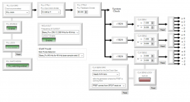
Your clock setup looks wrong, assuming you're not providing an external clock. See my screenshot attached.
I found it helps to test your outputs with an oscillator block before getting the inputs involved, one thing at a time.
Also check ASRC tab to see if you're getting a lock, and the SPDIF tab.
Is the word length correct? Mine is 24 bit
Attachments
Hello @xplo5iv, you just kindly answered a question on the LXmini forum. I replied to that one, but since I have no privileges there yet, I thought I'd ask here, since it's a better forum as well. I seem to have had your same idea, and I hope to be able to learn from your experience
It looks like you started with the Lusya board with the AD1938 codec board. Were you happy with the sound quality from that codec board or are you considering something else? I saw that some other projects based on the ADAU1452/67 use the AK4458 DAC, which seems to have better specs, but it's unclear to me how much sonic difference that could make
Do you plan to reuse the AD1938 board with your new ADAU1467, or look at something else?
The Lusya board is ok, but it ties up inputs that I wanted to use for other things, as I don't really need analogue in. There was some noise, but that was probably down to using USB power at the moment. (To be sorted later)
Going with the more stripped down board means I can play later with different DACs etc more easily, but more importantly I can easily run multiple digital inputs at the same time. (2 x USB, SPDIF is a minimum, but I also wanted Bluetooth. I'll probably add 1 analogue input).
The greater number of GPIOs also means using rotary encoders is easier, although I'm having a problem getting them to save to EEPROM at the minute...
Current version is using pots on the Aux ADCs, but I had a problem with noise, and rotary encoders seemed a better option, particularly if I later add a microcontroller for remote control.
Hello
@xplo5iv first of all I want to say a Big Thank You for your help!!!
the DSP is receiving and sending Data over Toslink.
As you expect to problem was the clock setup.
I never looked in the clock settings because I followed the instructions in the "EVAL-ADAU1452REVBZ User Guide" side 11.
This DSP stuff is so fascinating, but also so complicated.
Now I can go ahead with my project.
Thank Again!!
Yes, I can see how a different board would offer more flexibility, especially if you want to use more I/O from the ADAU itself (if I decide to also use a microprocessor, probably most of the UI would be handled by it, using a library like this to change the ADAU settings GitHub - MCUdude/SigmaDSP: A versatile Arduino library for interfacing with the ADAU1701 audio DSP (modified to support a different ADAU14xx from the current ASAU1701 only approach)The Lusya board is ok, but it ties up inputs that I wanted to use for other things, as I don't really need analogue in. There was some noise, but that was probably down to using USB power at the moment. (To be sorted later)
Going with the more stripped down board means I can play later with different DACs etc more easily, but more importantly I can easily run multiple digital inputs at the same time. (2 x USB, SPDIF is a minimum, but I also wanted Bluetooth. I'll probably add 1 analogue input).
The greater number of GPIOs also means using rotary encoders is easier, although I'm having a problem getting them to save to EEPROM at the minute...
Current version is using pots on the Aux ADCs, but I had a problem with noise, and rotary encoders seemed a better option, particularly if I later add a microcontroller for remote control.
Thanks for the info
Does anyone have the Lusya ADAU1452 schematics (DSP and codec board, ideally)? I searched all the posts here, but could only find the board and pin layout (the images in the listings), not the actual schematics.
I found the schematics for the ADAU1542/66 board from Mediaworks, but not the one with the codec option.
The reason I'm asking is that I would like to buy the ADAU1466 version (129KHz S/PDIF and more memory), but since no codec board is available for that one (and no multi-channel boards are available from the usual cheap sources), I would have to figure out how to connect the ADAU1466 to the AD1938 codec board. Most signals are straightforward, but the MCLK_IN and OUT are not entirely clear. They seem to be XTALIN/MCLK and CLKOUT directly from the ADAU1542 to the AD1938, which seems to lack the on-board crystal and relative circuit for clock generation. So basically the codec board seems to depend on the ADAU1452 for the clock, and would not work as a standalone board unless a proper clock is provided.
Very likely, it's just a matter of connecting the 1452_CLKO on pin 24 of JL from the ADAU1466 board to the MCLK_IN on the codec board. Assuming R31 on the codec board is a 0 Ohm resistor (i.e. a jumper) and assuming I followed the hazy JPG traces correctly
This can also be verified by using a continuity meter and checking that MCLK_IN on the codec board goes directly to pin 2 on the AD1938.
If so, the AD1938 codec board can be used with the Mediaworks ADAU1466 board. Probably would be easier to create a simple PCB to securely mate the two boards and provide the right routing and headers
- Home
- Source & Line
- Digital Line Level
- low cost ADAU1452 China board...