Already tried several USB cables, several blue CY7C68013A boards with 2 green DSP boards.
Same hardware on the same laptop in Windows 10 gives the USB communication error, in the VMWare Windows 7 virtual machine is working properly, both with SigmaStudio 4.7 🙂
I'm using the USB 2.0 ports on the laptop - on all 3 of them is the same.
The only difference is the operating system...
Same hardware on the same laptop in Windows 10 gives the USB communication error, in the VMWare Windows 7 virtual machine is working properly, both with SigmaStudio 4.7 🙂
I'm using the USB 2.0 ports on the laptop - on all 3 of them is the same.
The only difference is the operating system...
Hi @dzwer
I finally got it working, but I followed the instructions to install the driver on 3e Audio. Especially what is written at the end regarding Windows 10 and driver file signature. Attaching the link to 3e Audio.
https://www.3e-audio.com/dsp/adau1701-2in4out/
I finally got it working, but I followed the instructions to install the driver on 3e Audio. Especially what is written at the end regarding Windows 10 and driver file signature. Attaching the link to 3e Audio.
https://www.3e-audio.com/dsp/adau1701-2in4out/
Yes, on both machines I had to "Force Deactivation of Driver Signature" to install the drivers.
Have you checked other available addresses?ADDR1 is tied to 3.3V via pull-up resistor, ADDR0 is connected to GND, so the I2C address is 0x6C
Today everything works under Windows 10 and Windows 7...
The address of the DSP has to be set to 0x68...
I erased the EEPROMs of all my blue CY7C68013A boards - now they have only 0x00 everywhere.
Something important for those blue CY7C68013A boards:
- LCSOFT board with 1 jumper on it: the jumper should be placed, for its EEPROM address to be different than 0xA0;
- no name board with 2 jumpers on it: both jumpers should be removed, for its EEPROM address to be different than 0xA0.
This way I can first connect the programmer board and the DSP board and then to power up them together.
Why just noise?
I have sound for about 15 seconds but then it just becomes noise. What could be wrong? Input is spdif.
I have sound for about 15 seconds but then it just becomes noise. What could be wrong? Input is spdif.
Do you use my project? If yes it's probably because SPDiF signal is poor quality and program automatically switch to C/D input. You can omit this swich and connect SPDiF directly to, as I remember, to DC Block. This board is very sesitive to SPDiF quality.
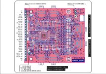
@frobek The split supply for opamps is very interesting. Congrats with very nice measurements!5V rails are connected so you can supply only one board as far as 3V3 rails are also connected together. In my project I split supply lines and built external power supply 2x5V and 3V3, than I obtain quite good distortion level. See below. Measurement made by REW using Motu M2 interface, balanced output and internal (DSP) 1kHz generator. The USBi is essential but you can go the cheap way:
https://www.diyaudio.com/community/...rammer-using-cypress-cy7c68013a-board.269111/
View attachment 1415536
Do you have the oppertunity to explain where you cut the lines so a negative supply could be used?
That is where it is cut so not -V is shorted to ground.
I am interested in using a +-12 Volt analog supply so if you know where to cut the positive lanes it is also very nice to know. (Without shorting +12V to +5V)
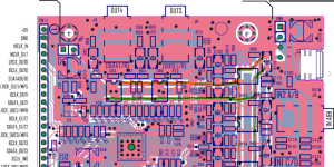
Now I undertand your setup.
Misunderstood the 2x5Volt centense. Wishfull thinking it was +/- 5 volts.
But then it can't be the OPA1612 version of the AD codec board? The OPA1612 don't work at 5 volt single supply? Or is it just the bad/unstable/noisy supply voltage of the unmodded boards?
Misunderstood the 2x5Volt centense. Wishfull thinking it was +/- 5 volts.
But then it can't be the OPA1612 version of the AD codec board? The OPA1612 don't work at 5 volt single supply? Or is it just the bad/unstable/noisy supply voltage of the unmodded boards?
I have fried my AD codec card with OPA1612, so can not verify, but this is very interesting.
I wonder if your modification of separating DSP card voltage source and codec card voltage source is enough. Will the result be OK by using USB power source on both and just cut the 5v link between the cards?
The strange thing is that the cs codec handles common power. Wonder why the opamps do not without really high distortion
Just for reference, my measurement of a unmodded AD combo https://www.diyaudio.com/community/threads/low-cost-adau1452-china-board.309680/post-7717061
Measurements made before I fried the AD card
Measurements made before I fried the AD card
Even not modified codec board looks much better then yours, sligtly worse than modified. IMHO your mesasurements looks like damaged or signal is distorted (to high).
I am not the only one that have the «bad board» https://www.diyaudio.com/community/threads/low-cost-adau1452-china-board.309680/post-7808251
we manage to get good signal out of modified boards AD or CS, but not the unmodified ones
Have you measured the commom mode voltage on the DACs. (The DC before the caps)
Have you measured the commom mode voltage on the DACs. (The DC before the caps)
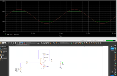
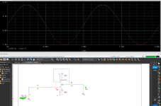
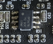
Another thing that is a little clumsy on this board is the OPA1612 with high input impedance. If the enclosed scheme still holds the circuit is like this.
Sallen key LP filter
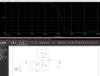
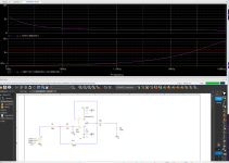
So really nice filter, but noise way to high for a 1612. Should have 1/10 of the values so the low voltage noise of the device could shine.
Like this.
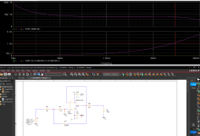
Guess they just had a surpluss of OPA1612s and used it instead of the original more rail friendly and high impedance ones
Sallen key LP filter


So really nice filter, but noise way to high for a 1612. Should have 1/10 of the values so the low voltage noise of the device could shine.
Like this.

Guess they just had a surpluss of OPA1612s and used it instead of the original more rail friendly and high impedance ones
Attachments
Last edited:
- Home
- Source & Line
- Digital Line Level
- low cost ADAU1452 China board...
