you miss the point , c13 before or after the lcr is not the same
If you put C13 after LCR, C13 should be 100u into 600 ohms, not 100n into 1Meg5. Of course we can still verify it.
Thank euro21.
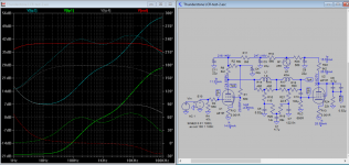
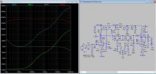
Now I have a few sim plots of LCR phono using E810F. It's a combined sch of zero bias of Thorsten and cap coupling of Thunderstone. I plot the input and output impedance at various test points to verify that they're technically correct, it's quite an exercise for me. Sonic wise you only know as you build it. Likewise I hope this help you to understand and raise appropriate questions. For example output impedance of input LCR driver has been raised so the combined Z is close to LCR input Z, do you agree?
why bias the tubes near of 0v , in this point the distortion is not higher?
why bias the tubes near of 0v , in this point the distortion is not higher?
Thunderstone has 56/1ku in the U1 E801f cathode, I put them in distortion goes up from 0.29% to 0.37% @ < 0.7V out, the gain drop almost by 3 db.
Koonw, are you "measure" current Ig1 through 600 ohm resistor at the output tube. It is unacceptable great, I guess.
Rg1_min should be about 50 Kohm for E810F and about 200 Kohm for D3a (for zero bias), if I remember correctly.
Also, it seems to me that E810F cathode current >30mA, and D3a current about 15 mA, on Thorsten schematic.
BTW, @euro21, for your E810F model you used Ug2 = 150V, right ??
Rg1_min should be about 50 Kohm for E810F and about 200 Kohm for D3a (for zero bias), if I remember correctly.
Also, it seems to me that E810F cathode current >30mA, and D3a current about 15 mA, on Thorsten schematic.
BTW, @euro21, for your E810F model you used Ug2 = 150V, right ??
Koonw, are you "measure" current Ig1 through 600 ohm resistor at the output tube. It is unacceptable great, I guess.
Rg1_min should be about 50 Kohm for E810F and about 200 Kohm for D3a (for zero bias), if I remember correctly.
Also, it seems to me that E810F cathode current >30mA, and D3a current about 15 mA, on Thorsten schematic.
BTW, @euro21, for your E810F model you used Ug2 = 150V, right ??
That is right: round(I(R1)*100k)/100k is 2.85mA, but I feel not quite right. Where is the datasheet of E801f Vg2=150 or 100V?
https://frank.pocnet.net/sheets/009/e/E810F.pdf
Personally, I would not change anything on Thorsten scheme.
Personally, I would not change anything on Thorsten scheme.
I'll sim again to verify thing when I found correct E801f model or I paint it.
Anyway here is to my friend question, there need one alternation in LCR unit to bypass DC if C13 is placed after LCR, have a look where is the difference? In U1 frequency response I see it is more smooth.
Anyway here is to my friend question, there need one alternation in LCR unit to bypass DC if C13 is placed after LCR, have a look where is the difference? In U1 frequency response I see it is more smooth.
Attachments
Last edited:
https://frank.pocnet.net/sheets/009/e/E810F.pdf
Personally, I would not change anything on Thorsten scheme.
I won't publish the SIM results for original Thorsten sch or any commercial product, you need to verify yourself.
😉 Not required.
Lab measurements for Thorsten LCR RIAA were available on the net a long long time ago.
Lab measurements for Thorsten LCR RIAA were available on the net a long long time ago.
😉 Not required.
Lab measurements for Thorsten LCR RIAA were available on the net a long long time ago.
Could be just another measurement by whom🙄 ?, no harm to measure again esp when you have built one yourself, it's you yourself or lab data you ought to agree with!
BTW, @euro21, for your E810F model you used Ug2 = 150V, right ??
It's no "mine", Stephie Bench published it in the Intactaudio forum (tetrode.txt).
:: View topic - Updated TETRODE.TXT file
It's no "mine", Stephie Bench published it in the Intactaudio forum (tetrode.txt).
:: View topic - Updated TETRODE.TXT file
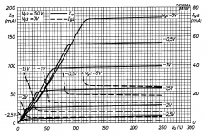
Plot looks close enough to original, both plate and screen current, I just can't paint one like that. We will use this one.
Attachments

Koonw, are you "measure" current Ig1 through 600 ohm resistor at the output tube. It is unacceptable great, I guess.
Rg1_min should be about 50 Kohm for E810F and about 200 Kohm for D3a (for zero bias), if I remember correctly.
Also, it seems to me that E810F cathode current >30mA, and D3a current about 15 mA, on Thorsten schematic.
BTW, @euro21, for your E810F model you used Ug2 = 150V, right ??
What is the problem if want to use a MC and load the Rg1 with 200ohm, too far of 50k or 200k for D3a,
I have got problems of HF roll off in 6sl7 by miller effect over 10khz with 220k load and 14khz with 150k, why don´t use the miller effect as complement of the RIAA
What is the problem if want to use a MC and load the Rg1 with 200ohm, too far of 50k or 200k for D3a,
I have got problems of HF roll off in 6sl7 by miller effect over 10khz with 220k load and 14khz with 150k, why don´t use the miller effect as complement of the RIAA
True, those who used grid leak bias i.e, cathode is shorted to ground, then the grid leak resistor needs to be very large, as there is about -2V on the grid for 12ax7, no just zero and have to use a DC block capacitor in the input. We're not grid leak, just zero bias, I think we should avoid that. You can use DC blocking cap and larger resistor if need to, provided you don't get a negative voltage on the grid. That is IMO.
Last edited:
I have further massaged e810f model and now bring into real close to the original. You can see where I have made the changes KG1, KP, KVB which fine tube the spacing and height, and formula G2 4 3 value= {(I(G1)*30/(V(1,3) + 30))} ; fine tune screen current, changed from *39
.SUBCKT E810F 1 2 3 4 ; P G K G2
+ PARAMS: CCG=3P CGP=1.4P CCP=1.9P RGI=1000
+ MU=57 KG1=106 KP=1200 KVB=13 KVC=2.24 VCT=0.144 EX=1.4 KG2=370.1
* Vp_MAX=250 Ip_MAX=200 Vg_step=0.5 Vg_start=0 Vg_count=6
* Rp=1600 Vg_ac=23.5 P_max=5 Vg_qui=-23.4 Vp_qui=240 UL=0.43 EG2=150
* X_MIN=97 Y_MIN=47 X_SIZE=904 Y_SIZE=726 FSZ_X=1792 FSZ_Y=895 XYGrid=true
* showLoadLine=n showIp=y isDHP=n isPP=n isAsymPP=n isUL=n showDissipLimit=y
* showIg1=y gridLevel2=n isInputSnapped=n
* XYProjections=n harmonicPlot=y harmonics=y
*----------------------------------------------------------------------------------
RE1 7 0 1G ; DUMMY SO NODE 7 HAS 2 CONNECTIONS
E1 7 0 VALUE= ; E1 BREAKS UP LONG EQUATION FOR G1.
+{V(4,3)/KP*LOG(1+EXP((1/MU+(VCT+V(2,3))/V(4,3))*KP))}
G1 1 3 VALUE={limit((PWR(V(7),EX)+PWRS(V(7),EX))/KG1*1.57*ATAN(2*V(1,3)/(KVB*3.14159)),0,v(1,3)/710)}
; added limit-better models lower plate voltage limit condion
G2 4 3 value= {(I(G1)*30/(V(1,3) + 30))} ; changed from *39
E2 8 4 VALUE={0} ; Dummy
RCP 1 3 1G ; FOR CONVERGENCE
C1 2 3 {CCG} ; CATHODE-GRID 1
C2 1 2 {CGP} ; GRID 1-PLATE
C3 1 3 {CCP} ; CATHODE-PLATE
R1 2 5 {RGI} ; FOR GRID CURRENT
D3 5 3 DX ; FOR GRID CURRENT
.MODEL DX D(IS=1N RS=1 CJO=10PF TT=1N)
.ENDS
*$
Attachments

Last edited:
Would it be possible to contruct a 600 Ohm RC EQ?LCR RIAA ?!?
no thanks, too expensive for me 😀
Then one could build a good phono stage (except for the EQ of cause) and later, if and when funds permit, buy a good LCR as a "drop in replacement". 😀
Yes, it's a possibility 😎
But, if I decided to make a LCR RIAA, it would be 1k5 (or higher) LCR.
But, if I decided to make a LCR RIAA, it would be 1k5 (or higher) LCR.
this
http://www.diyaudio.com/forums/tubes-valves/287456-my-latests-well-first-riaa-preamp.html
I am happy with it
http://www.diyaudio.com/forums/tubes-valves/287456-my-latests-well-first-riaa-preamp.html
I am happy with it
- Home
- Source & Line
- Analogue Source
- Looking for the best SQ Phono LCR schematic