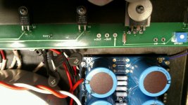
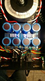
The F1J does not have a bipolar supply like many other FW amps, so each channel has its own secondary winding and its own bridge rectifier and filter caps. The caps across the rectifiers' outputs are additional smoothing caps. The idea is to have a cap as close to the rectifiers as possible.
Thanks, so basically it doesn’t hurt to have this cap on my other pass builds where I use the bridge rectifiers and CRC PSU even though bipolar. Also is the voltage of the cap based on the secondary rating of the trafo?
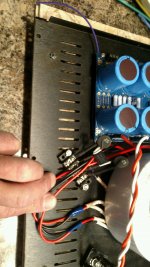
Toroidy supply neoprene pads to go under their transformers. Seems considerably denser than silicon so I'm not sure it works quite as well, but it seems to work well enough -- and doesn't have the dis-mounting issue.
Accesories - Shop Toroidy.pl
Accesories - Shop Toroidy.pl
I actually put a ring of neoprene, that has some self adhesive on one side, around the circumference of the rubber pad to hold it up off of the wires.
I am going to place an order for a transformer rated at 0-18v @8.5A with 2 secondaries. So a total of around 300VA and use my CRC PSU board with bridge rectifiers.
Thats interesting Jeff, please provide more details of the cap value/voltage and how its connected to the IEC socket (hot/neutral/ground)
Thanks
Thanks
The cap is across hot/neutral. It therefore MUST be a Class-X rated cap (I use an X2).
I don't think the value matters much. I use 3300pF.
I don't think the value matters much. I use 3300pF.
The cap is across hot/neutral. It therefore MUST be a Class-X rated cap (I use an X2).
I don't think the value matters much. I use 3300pF.
I use a CL-60 thermistor in series with the hot side for the same. What is the difference using a Class X2 cap or a thermistor if the purpose is same of mains suppression/soft start?
Thanks
The thermistor is for soft start while the x2 cap is for suppression.
So its more like RFI/EMI suppression is it?
Two different purposes: the series CL-60 thermistor is for soft-start; the parallel cap is for EMI/RFI suppression (both into and out of the amp).
I moved mine to the IEC as well, just made sense to do it that way.
Taking a couple of days off from work so I hope to have things close to completed today.
Having a hard time sourcing some speaker jacks though, it seems everybody is out of them except the ubber expensive ones
Taking a couple of days off from work so I hope to have things close to completed today.
Having a hard time sourcing some speaker jacks though, it seems everybody is out of them except the ubber expensive ones
I use 24AWG on the signal side. Some guys like even finer stuff, but I worry about mechanical issues if it gets bumped.
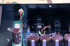
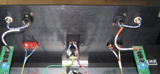
Got the boards wired to the PSU.
So onto the XLR and RCA connectors, wired XLR connectors, just want to know if I have this right, positive to pin 2 on XLR and jumpered to positive on RCA.
Negative to pin 3 on XLR.
Negative from RCA to pin 1 of XLR.
Also, are there any posts about setting DC offset?
Thanks, Greg
So onto the XLR and RCA connectors, wired XLR connectors, just want to know if I have this right, positive to pin 2 on XLR and jumpered to positive on RCA.
Negative to pin 3 on XLR.
Negative from RCA to pin 1 of XLR.
Also, are there any posts about setting DC offset?
Thanks, Greg
The manual for the J2 states pin 1 ground, pin 2 positive, pin 3 negative.
If a ground reference point was available at the board, why was it not used.
If a ground reference point was available at the board, why was it not used.
- Home
- Amplifiers
- Pass Labs
- Long skinny builders thread