What brand input capacitor will you use? I looked, there is a choice of 3 brands suitable for audio use.
1. Nichicon ES
2. Elna RBD
3. Audio Note Seiryu (too expensive, but probably the best and will also match nicely to the black pcb)
.... 🤢
1. Nichicon ES
2. Elna RBD
3. Audio Note Seiryu (too expensive, but probably the best and will also match nicely to the black pcb)
.... 🤢
Mur460s are 4A , so total 16A.Yes, I'm planning full dual mono...
I would replace the originally used 1N5408 with MUR460, I think the current reserve will be sufficient,...
I just can't estimate what the charging current of the capacitors will be when switched on. (40.000 uF/per channel)
What brand input capacitor will you use? I looked, there is a choice of 3 brands suitable for audio use.
1. Nichicon ES
2. Elna RBD
3. Audio Note Seiryu (too expensive, but probably the best and will also match nicely to the black pcb)
.... 🤢
I ordered Nichicons
Ok, I think I am going to complicate this situation here a little bit more. I want to separate the input stage from the power stage into separate PCBs. For input stage I am thinking to add signal selector switch that will toggle between balanced and unbalanced inputs. In that way I can have nice low noise unbalanced inputs. For the balanced inputs I am looking to implement a good quality instrumentation input stage. All of these were to go on a separate PCB. In that way I can move LM317 and LM337 power regulators from the main LM3886 board and sort of declutter it from the low signal input stage.
Attachments
I have updated resistor values for the input opamp.
I suggest you use those.
Now the unbalanced inputs is -10 dBu level - typical for the RCA phono connectors.
Balanced inputs level is +4 dBu.
Both levels are required to get full power out of the amplifier without clipping.
In addition, you have Gain potentiometer that will only attenuate signal down in volume.
Stability capacitors were also fine tuned with this specific gain adjustment.
Attachments

Last edited:

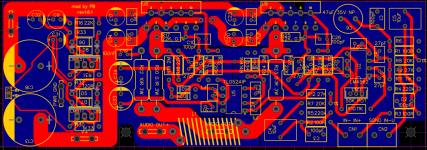
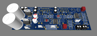
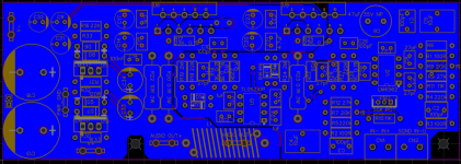
Latest update on this one with better ground plains and proper decoupling for each chip.
For input buffer and servo opams decoupling capacitors were connected to the signal ground - is that bad? will it introduce power supply ripple into a low signal ground at all?
For input buffer and servo opams decoupling capacitors were connected to the signal ground - is that bad? will it introduce power supply ripple into a low signal ground at all?
Attachments
I am thinking about splitting the schematics into two separate modules: preamp and power amp.
Attached schematics are for both.
Setting gain to 10V/V is the minimum gain required according to the datasheet. Will it negatively impact stability or any other characteristics of the LM3886 to do so?
Thanks,
Pavlo
Attached schematics are for both.
That would be dBu not dB. Or so I'm assuming anyway. dB without a reference is meaningless unless we're talking unit-less ratios such as gain.
+4 dBu = 1.23 V RMS
-10 dBu = 245 mV RMS
Handy-dandy calculator: http://www.sengpielaudio.com/calculator-db-volt.htm
Common gains are:
+23 dB (= 14.1 V/V) for balanced
+29 dB (= 28.2 V/V) for unbalanced
+26 dB (= 20 V/V) used to be very common but I get the sense that 23 and 29 dB have taken over. I usually design for 20 dB (= 10 V/V) for better gain structure.
Tom
Setting gain to 10V/V is the minimum gain required according to the datasheet. Will it negatively impact stability or any other characteristics of the LM3886 to do so?
Thanks,
Pavlo
You can run the LM3886 with 20 dB gain (10 V/V). You just have to be a bit careful with the not-so-optional stability components (Cc, Cf, and Rf2 in the data sheet) if you do that.
The TI simulation model doesn't capture the behaviour near the supply rails, so you'll have to experiment a bit once you build the circuit. Just run a sine wave into the amp and apply a 4 Ω load. Slowly dial up the amplitude until the amp approaches clipping. It should clip cleanly without buzz on the waveform.
Tom
For input capacitors the best would be film type. Wima, Kemet, Panasonic or other. Values are usually small for those.What brand input capacitor will you use? I looked, there is a choice of 3 brands suitable for audio use.
1. Nichicon ES
2. Elna RBD
3. Audio Note Seiryu (too expensive, but probably the best and will also match nicely to the black pcb)
.... 🤢
For bigger values like 100uf , non polar electrolytic capacitors are the only choice. With 47uF or 100uF they are filtering frequencies that are way lower/higher from the 20-20k range. Those capacitors are to block DC voltage and that is all. No useful filtering is done by them as they introduce distortion at the frequencies they affect as filter.
As I progress learning more the schematics is being changed to reflect that new information.
For the input levels I think I finally got it. Two levels +4 dBu and -10 dBV. Also, +4 can be balanced or unbalanced. From what I understand, balanced level means double voltage, so in total it is 2*4 = 8 dBu.
As far as connectors, you have XLR or TRS jack that are used for balanced interconnections. You also have RCA phono connector that can either carry +4dBu level or typically -10dBV level signal.
According to that, the latest changes to the schematics are as follows:
- for unbalanced RCA inputs the input buffer gain was set to ~x4 to bring -10 dBV signal to the proper level
- for balanced XLR or TRS inputs attenuating resistors' values were adjusted to gain of x0.7 (21k/30k). (to set gain to x0.5 increase 30k resistors to 39k or 43k)
- gain for both LM3886 was set to 16V/V
All of those are for the 50K gain potentiometer adjusted to the max. Adjusting it to the min allows for wide variety of inputs to be connected to the amp.
Servo resistors were updated as well.
Attachments
Last edited:
I just found out that so called balanced output of the Rolls RM67 is a "fake" one! It is done using resistors only! Not proper inverting opamp!
Attached is a screenshot.
I am thinking now to simplify the design now since I do not need balanced inputs in my amplifier. All I need is just input buffer.
Attached is a screenshot.
I am thinking now to simplify the design now since I do not need balanced inputs in my amplifier. All I need is just input buffer.
Attachments
Last edited:
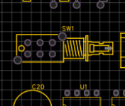
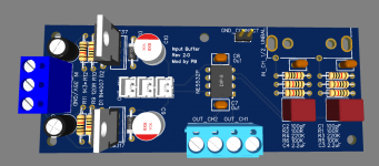
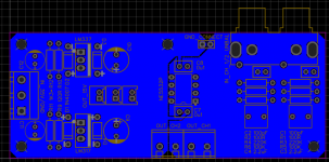
Input Buffer Module is a separate board now. It includes input audio filtering, voltage follower opamp, and power regulation.
This is designed to be used together with the main amp board.
The gain is set to none since this is a voltage follower.
This is designed to be used together with the main amp board.
The gain is set to none since this is a voltage follower.
Attachments

Last edited:
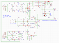
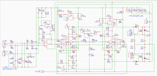
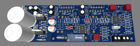
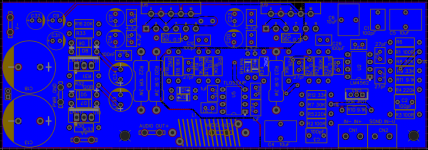
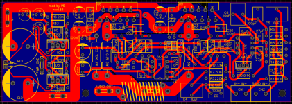
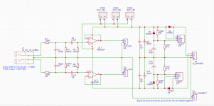
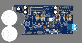
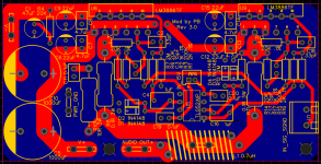
Power Amp Module is a separate PCB board now. It includes two LM3886 chip amplifiers connected in parallel. Audio signal from the previous board is fed to the inverting inputs of both chips. The board also includes DC servo circuit.
The gain is set to 20 V/V. With +-35V supply amplifier will develop the full power output if fed +4 dBU level input signal.
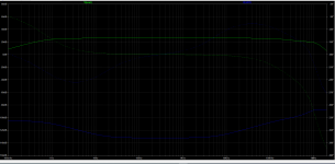
All resistors and capacitors were adjusted using LTSpice simulation to give optimal frequency response.
The gain is set to 20 V/V. With +-35V supply amplifier will develop the full power output if fed +4 dBU level input signal.
All resistors and capacitors were adjusted using LTSpice simulation to give optimal frequency response.
Attachments

Last edited:

That's pretty common. Some call it "impedance balanced". It's still a proper balanced out as there is no need to actively drive both signal lines unless you need the extra voltage swing. Here's a nice article by Bruno Putzeys that addresses this.I just found out that so called balanced output of the Rolls RM67 is a "fake" one!
That's pretty common. Some call it "impedance balanced". It's still a proper balanced out as there is no need to actively drive both signal lines unless you need the extra voltage swing. Here's a nice article by Bruno Putzeys that addresses this.
I am assuming that I can just use one of the output signals to drive my amplifier - all I need is a Tip and Sleeve portion of the TRS jack out - connected to the innner and gnd of the RCA input of my power amp. I am expecting +4dBU output level signal. Is that correct?
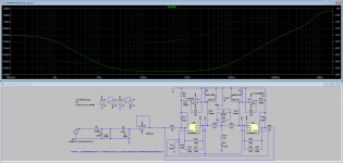
It probably makes no difference in practice simply because you have a DC servo to correct any offsets. When the amp is built for real then ideally you want a value of resistor that gives 0.00 volts DC at the output of the servo opamps. In the simulation the DC voltage is around 1.2 volts with a 2k2 and half that with a 1k. Remember you have up to -/+ whatever the opamp supply is as a correction voltage and so its a non issue.
Here is 2k2 and 1k
View attachment 1030867
Playing with servos a little more here. It looks like those resistors limit the amount of correction servos can apply. For example, I had a circuit where DC offset voltage at the input of the LM3886 presented was +170mV. With 2K resistor servo could only provide -110mV and with 1K only -56mV. Adjusting resistor to 4K7 fixed that to be -170mV.
Also, wierd way LTSpice was acting when I used 1k, 2k, 4.7k resistors - was running super slow and loading the PC a lot. Only 6.2k resistor value fixed the circuit and LTSpice was able to run fast again.
Some values can be slow to converge, it's an LT thing and sometimes altering a value by even a few ohms makes a big difference.
If the basic circuit has an intrinsically high DC offset then you have to decide whether you are actually using the servo to correct the offset of whether the 'servo' has actually become more of a bias source for the amp.
If the basic circuit has an intrinsically high DC offset then you have to decide whether you are actually using the servo to correct the offset of whether the 'servo' has actually become more of a bias source for the amp.
Found this video from audio science review on balanced vs unbalanced connections and I'm thinking now how would I go about changing the schematics to the balanced back again...
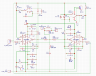
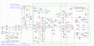
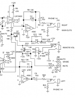
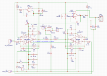
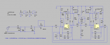
Here is a different approach that considers balanced inputs. It is just to illustrate the concept ("+", GND, and "-" are not connected between each chip)
I wonder if there is any way to implement servos in this schematics to remove DC offset at the output of the LM3886s?

I wonder if there is any way to implement servos in this schematics to remove DC offset at the output of the LM3886s?
- Home
- Amplifiers
- Chip Amps
- LM3886 in parallel with servo circuit build attempt