is this really important if you then have an amp (LM3886) that will add 0.01 % THD anyway?THD is pretty low at 0.00005%
just a thought ...
Last edited:
is this really important if you then have an amp (LM3886) that will add 0.01 % THD anyway?
just a thought ...
I guess I'm just wondering if the the servo will add it's THD to the 0.01% of the lm3886?
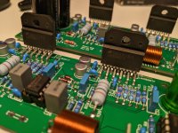
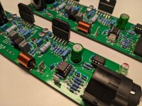
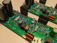
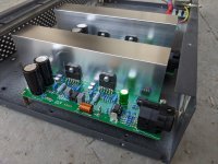
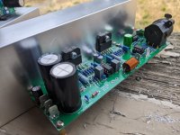
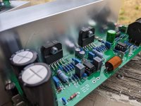
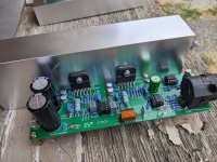
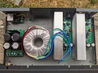
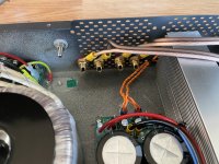
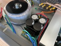
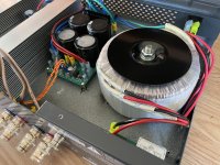
Parts and boards are in so this project has is in progress!
Attachments
-
 PXL_20220809_205959683.jpg422 KB · Views: 184
 -
 PXL_20220809_210034197.jpg460 KB · Views: 182
 -
 PXL_20220809_210004342.jpg391.4 KB · Views: 172
 -
 PXL_20220809_205940346.jpg425.6 KB · Views: 176
 -
 PXL_20220809_205932249.jpg410.9 KB · Views: 177
 -
 PXL_20220809_205946165.jpg415.5 KB · Views: 171
 -
 PXL_20220809_205943544.jpg479.5 KB · Views: 178
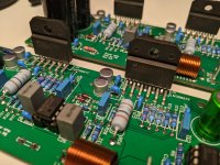
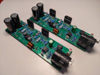
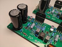
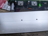
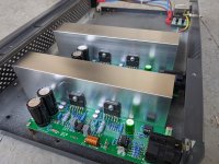
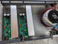
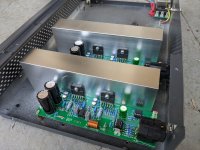
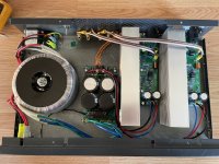
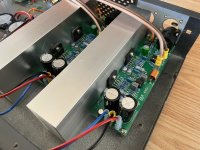
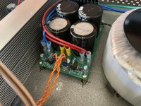
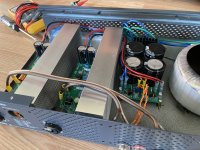
Heatsinks are attached!
Attachments
-
 PXL_20220809_212012345.jpg386.6 KB · Views: 149
 -
 PXL_20220809_222743269.jpg432.1 KB · Views: 149
 -
 PXL_20220809_212145880.jpg333.1 KB · Views: 151
 -
 PXL_20220809_222752871.jpg489.8 KB · Views: 164
 -
 PXL_20220809_222755562.jpg466.5 KB · Views: 160
 -
 PXL_20220809_220050246.jpg440.3 KB · Views: 152
 -
 PXL_20220809_220053012.jpg416.6 KB · Views: 152
 -
 PXL_20220809_220103678.jpg555.2 KB · Views: 153
 -
 PXL_20220809_222625878.jpg647.8 KB · Views: 148
 -
 PXL_20220809_212007921.jpg381.2 KB · Views: 137
 -
 PXL_20220809_222800169.jpg506.9 KB · Views: 144

Looks like a lot of work and components for a problem that could have been fixed with a simple bridged amp.Pardon me for asking, but whats the purpose of paralleling two chips?
Did you find one not to be adequate? You need double current? Tough speaker load?
Why not three in parallel? Its been published and tested. Or six.
Or chip with extra bjt on output to boost the current.
Or just adequate discrete design.
Complicated isnt always better.
I could go with a discrete design and that would get me more power - 100W to 300W. Probably would be simpler (or more tunable, customizable).Looks like a lot of work and components for a problem that could have been fixed with a simple bridged amp.
Complicated isnt always better.
Thoughts behind the above solution:
Bridging two LM3886 limits output current. Cannot work with 4ohm loads.
Paralleling two LM3886 doubles the current. Better load capability. Using them both in inverted mode decreases common mode distortion (slightly).
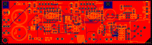
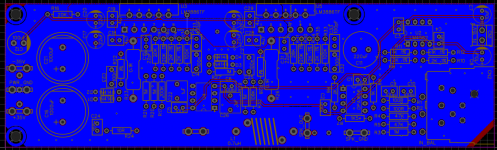
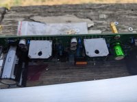
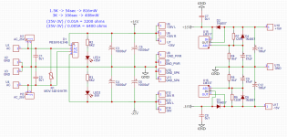
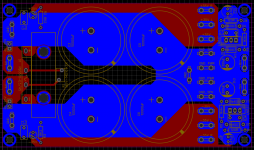
Had to fix power supply layout - was using incorrect pinout for LM337 voltage regulator. I wonder why designers decided to go with two different pin layouts for LM317 and LM337...
Attachments

The most positive power element "must" go to the center leg and the mounting tab. That's how old chips cook-out, like an NPN power transistor's collector is the package. (For the last 30 years this can be violated, but many of our fave chips are really really old designs.)why designers decided to go with two different pin layouts
Yes, many builders have run aground on these pinouts.
Actually, ICs have the lowest (or most negative) potential on the die substrate and, hence, on the metal tab.The most positive power element "must" go to the center leg and the mounting tab.
I think that has more to do with how a bipolar transistor is fabricated. Usually the base region is implanted into the collector substrate. Then the emitter is implanted into the base 'tub'. This is done to get as thin a base region as possible, thereby getting the highest current gain (beta). At least that's been the case in the processes I've worked in. Discrete devices are often a bit more involved.That's how old chips cook-out, like an NPN power transistor's collector is the package.
The only time I've ever seen a lateral BJT was in a CMOS process where a crappy BJT was offered so one could make bandgaps and such. Beta was maybe 10 on a good day. With some luck above one... 🙂
Tom
Yep. Always check the data sheet.Yes, many builders have run aground on these pinouts.
Tom
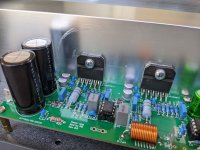
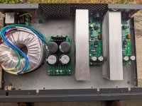
Amp is finally finished! Measured for correct power supply voltages and dc at the speaker terminals. All seems to be fine. Plugged to my speakers and it sounds great!
Next step will be measuring thd.
Next step will be measuring thd.
Attachments
-
 2AC982A6-2202-45A3-B7B1-C9D9C8538227.jpeg612.4 KB · Views: 144
 -
 5B175D07-7BD0-46ED-9790-6D13558EF8C1.jpeg557.6 KB · Views: 131
 -
 9307F0D4-015E-4D5A-9A67-08FD688024C7.jpeg445.6 KB · Views: 116
 -
 98F63F40-9CDF-4F2E-BE80-81D8DE114D11.jpeg494.6 KB · Views: 120
 -
 8242C703-C35D-4848-AC48-DA5FAC58586A.jpeg599.3 KB · Views: 122
 -
 572FCA28-2E95-4E50-B2CC-C5245C8D9AFA.jpeg562.7 KB · Views: 124
 -
 EB2F64FA-DFB3-49AD-91AD-4DA13602E207.jpeg620.2 KB · Views: 133
Last edited:
I finally had a chance to measure frequency response for the amplifier build. Few interesting points from the result - simulation for the frequency response in TinaTI was spot on. Roll off towards both ends of the spectrum (20Hz, 20,000Hz) is about 1dB.
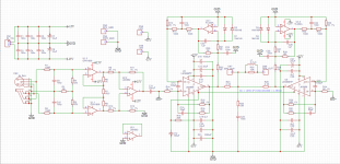
What is puzzling is the phase response. Since both LM3886 chips are inverted, the phase should be negative 180 degrees. But it is not. There are two strange occurrences where the phase shifts from -180 to 180 deg in the frequency range from 300 Hz to 3000 Hz and second region from 7kHz to 8kHz.
Can anyone help me to fix this? Any ideas where should I look and what to check?
Much thanks!

Below is the schematics implemented:

What is puzzling is the phase response. Since both LM3886 chips are inverted, the phase should be negative 180 degrees. But it is not. There are two strange occurrences where the phase shifts from -180 to 180 deg in the frequency range from 300 Hz to 3000 Hz and second region from 7kHz to 8kHz.
Can anyone help me to fix this? Any ideas where should I look and what to check?
Much thanks!
Below is the schematics implemented:
What is the physical meaning of this?the phase shifts from -180 to 180 deg
Stand on a compass at N. Walk 180 degrees to the right. Do again but walk 180 degrees to the left. Where do you end up?
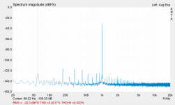
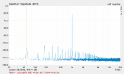
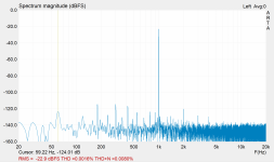
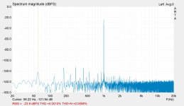
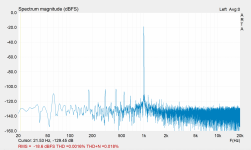
I measured THD and THD+N today using ARTA.
I am not sure what to make of those graphs. I used a few different settings for the volume out and mic in on my sound interface. I also used averaging on some graphs.
My guess is that I need to use regulated power supply to get rid of all the spikes in the graph. Even though they are below 110dB mostly.
Attachments

It will if you're not careful with the cutoff frequency of the servo. If the DC offset has enough output within the audio band it can raise the THD floor of the amp overall.I guess I'm just wondering if the the servo will add it's THD to the 0.01% of the lm3886?
Tom
- Home
- Amplifiers
- Chip Amps
- LM3886 in parallel with servo circuit build attempt