I got the idea from https://www.diy-hifi-forum.eu/forum/showthread.php?10114-Balanced-Endstufen-mit-Chipamp
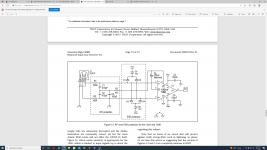
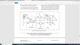
also from the article "The G World" with the schematics below:

also from the article "The G World" with the schematics below:
After exploring many other options I return to this thread with another schematics. I used THAT120x based chips to do the work of the difference amplifier. The chip has excellent CMRR. The signal is then goes to two LM3886 in parallel with servos. LM3886 are inverted to get better distortion performance. That is because I am not using composite amp topology - in my opinion inverted is better way to go.
Attachments

After exploring many other options I return to this thread with another schematics. I used THAT120x based chips to do the work of the difference amplifier. The chip has excellent CMRR. The signal is then goes to two LM3886 in parallel with servos. LM3886 are inverted to get better distortion performance. That is because I am not using composite amp topology - in my opinion inverted is better way to go.
Have you built it or still at the design point?
At this point I am trying to figure out servos configuration for the low gain of 10 for the LM3886. Servos worked fine with the gain of 22, but if I were to feed balanced signal from my Topping DAC, the level is 4V RMS - need low gain of 10 for that.
I am also considering including a DC blocking capacitor right after THAT IC.
So yes, still in the design stage.
I am also considering including a DC blocking capacitor right after THAT IC.
So yes, still in the design stage.
Last edited:
The DC servo is a lowpass filter with a cutoff frequency of (in your case) 1/(2*pi*2.2e-6*1e6) = 72 mHz. This is a bit more than two decades below 20 Hz, so figure the filter will attenuate a bit over 40 dB at 20 Hz. With the LM3886 that could be enough that the DC servo doesn't add any measurable contribution within the audio band. Whether it is enough will likely need to be determined by measurement as THD tends to not simulate reliably.
I originally had a 1st order DC servo similar to yours in the Modulus-86 Rev. 1.0. I found the output of the DC servo degraded the THD at low frequency and had to push the servo pole down to 12 mHz to push the THD added by the DC servo below the noise floor. This resulted in a rather long settling time (minutes!) so for Modulus-86 Rev. 2.0 I designed a 3rd order DC servo (-60 dB/dec filter slope). I found multiple feedback filters handy for this. TI has a good application note on the topic (https://www.ti.com/lit/an/sloa049b/sloa049b.pdf).
Granted, with the Modulus-86 I apply error correction to the LM3886 so I get much lower THD. This causes things like the DC servo to pop up as a contributor to THD. It's entirely possible that you don't need to worry about this. I'm just bringing it up as something to look for as it can be a trap if you allow it to be.
Tom
I am trying to reduce the gain of the LM3886 to 10 V/V.
By running simulation in the LTspice, it is clear that servos' configuration that works for the LM3886 gain of 21 V/V does not work with the gain of 10 V/V.
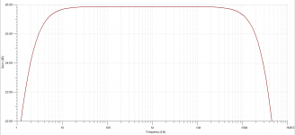
I added a low pass filter in front of the integrator circuit - frequency response seems to be satisfactory.
I have never done anything like this, so I am not sure if it will work properly?
Thank you
Attachments

Last edited:
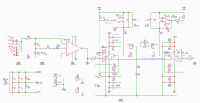
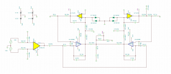
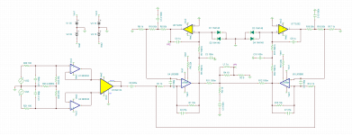
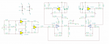
I keep returning to the original schematics that I made at the beginning. I want input to be balanced. I also want servos to correct for any DC offset.
For the first stage I decided to use difference amplifier IC INA134.
Two LM3886 are in parallel and are inverted.
Two servos are JFET input TL072 or TL052.
Attached is zipped TINA TI simulation file.
For the first stage I decided to use difference amplifier IC INA134.
Two LM3886 are in parallel and are inverted.
Two servos are JFET input TL072 or TL052.
Attached is zipped TINA TI simulation file.
Attachments
Hhm, a few thoughts...
1) parelleling servos is tricky. They really must have the same gain and the same time-constants to better than a few %, otherwise there will be large cross-currents while the response is settling after at DC offset change (and/or at power-up) as each section settles in a slightly different fashion.
2) 2nd order servos are also pretty tricky in their own regard. It is very easy to get a lot of overshoot if not outright oscillation at a very low frequency. Near DC, your inverting circuit of the LM3886 goes down close to 6dB, adding phase in the servo loop... which is already approaching -180deg from the 2nd order design.
You'd need to do a loop-gain analysis of the servo loop. As a simple check, look at the time response (transient analysis) of a step change at the input, spanning a least a minute or so.
This will make both issues visible for inspection. You could also check the FR of system and servo at near DC as well, starting the analysis and the plot at 1mHz or so
Did a sim of the servo.
Looks like the loop gain is low enough to not cause any problems:


Output settles quickly with no overshoot but servo output settles very slowly.
Now, looking at the servo response on a step change in output DC offset of the main amp:


Hhm, the servo takes many minutes to settle and to finally compensate the assumed 100mV output change. Offset has reduced to only 50% after a whopping 3 minutes. The ratio R5/R4 creates a time constant multiplier here, sort of.
So, once we manage to ever throw off the low internal offsets by, for example, one stage clipping first (unlikely both sections would go into clipping exactly the same way) it will take a long time for these to null again, differentially. And the moment the main loop opens the servos themselves go open-loop as well (the diode shunts will shorten recovery time, but still...)
---------
I now recognized you kept ratios and time constants, as well as general servo design, along the example circuit in the TI appnote so it should be basically safe to use. The appnote sadly does not tell us how the servos will clip and recover, however.
Looks like the loop gain is low enough to not cause any problems:
Output settles quickly with no overshoot but servo output settles very slowly.
Now, looking at the servo response on a step change in output DC offset of the main amp:
Hhm, the servo takes many minutes to settle and to finally compensate the assumed 100mV output change. Offset has reduced to only 50% after a whopping 3 minutes. The ratio R5/R4 creates a time constant multiplier here, sort of.
So, once we manage to ever throw off the low internal offsets by, for example, one stage clipping first (unlikely both sections would go into clipping exactly the same way) it will take a long time for these to null again, differentially. And the moment the main loop opens the servos themselves go open-loop as well (the diode shunts will shorten recovery time, but still...)
---------
I now recognized you kept ratios and time constants, as well as general servo design, along the example circuit in the TI appnote so it should be basically safe to use. The appnote sadly does not tell us how the servos will clip and recover, however.
A few critiques:
R18 is not needed.
Unless I'm thinking about this wrong, I'm not sure the DC blocking cap (C9) is of much use in this case. Since the LM3886 inputs are tied together, the DC gain is only reduced to 5 rather than unity. The INA134 has very low voltage offset, so I think it would make more sense to get rid of C9 and block DC at the INA134 inputs.
Without input buffers, this input stage will be very sensitive to source impedance mismatch because the common-mode input impedance is low. CMRR will degrade vs the theoretical 90dB with only 2 ohms of mismatch. 20 ohms of mismatch degrades the CMRR to 68dB.For the first stage I decided to use difference amplifier IC INA134.
Using a TL072 for the servo doesn't make much sense to me as the input offset voltage specs aren't that great. In fact, the typical spec is worse than the LM3886 for all variants (though the maximum is lower for the AC, BC, and I). TL052 has better DC specs.Two servos are JFET input TL072 or TL052.
R18 is not needed.
Unless I'm thinking about this wrong, I'm not sure the DC blocking cap (C9) is of much use in this case. Since the LM3886 inputs are tied together, the DC gain is only reduced to 5 rather than unity. The INA134 has very low voltage offset, so I think it would make more sense to get rid of C9 and block DC at the INA134 inputs.
A few critiques:
Without input buffers, this input stage will be very sensitive to source impedance mismatch because the common-mode input impedance is low. CMRR will degrade vs the theoretical 90dB with only 2 ohms of mismatch. 20 ohms of mismatch degrades the CMRR to 68dB.
Using a TL072 for the servo doesn't make much sense to me as the input offset voltage specs aren't that great. In fact, the typical spec is worse than the LM3886 for all variants (though the maximum is lower for the AC, BC, and I). TL052 has better DC specs.
R18 is not needed.
Unless I'm thinking about this wrong, I'm not sure the DC blocking cap (C9) is of much use in this case. Since the LM3886 inputs are tied together, the DC gain is only reduced to 5 rather than unity. The INA134 has very low voltage offset, so I think it would make more sense to get rid of C9 and block DC at the INA134 inputs.
Thank you for the input!
Regarding INA134 - I might just go with THAT1203 IC instead. Those have input buffers as well as bootstrap technique for big common mode impedance.
Thank you for taking your time and making those simulations! Do you mind posting those LTspice sim files?Did a sim of the servo.
Looks like the loop gain is low enough to not cause any problems:
View attachment 1068160
View attachment 1068161
View attachment 1068163
Output settles quickly with no overshoot but servo output settles very slowly.
Now, looking at the servo response on a step change in output DC offset of the main amp:
View attachment 1068164
View attachment 1068165
View attachment 1068166
Hhm, the servo takes many minutes to settle and to finally compensate the assumed 100mV output change. Offset has reduced to only 50% after a whopping 3 minutes. The ratio R5/R4 creates a time constant multiplier here, sort of.
So, once we manage to ever throw off the low internal offsets by, for example, one stage clipping first (unlikely both sections would go into clipping exactly the same way) it will take a long time for these to null again, differentially. And the moment the main loop opens the servos themselves go open-loop as well (the diode shunts will shorten recovery time, but still...)
---------
I now recognized you kept ratios and time constants, as well as general servo design, along the example circuit in the TI appnote so it should be basically safe to use. The appnote sadly does not tell us how the servos will clip and recover, however.
TI AN has 0.47uF and 2.2Meg - settling time of 1 sec?
Changed servo's configuration. Reduced the capacitance of the first filter cap to 0.47uF. Integrator cap is 2.2uF. Added 0.1uF cap after the servo - looks like it fixed the phase at the higher frequencies.
Attachments
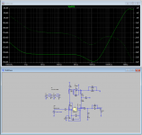
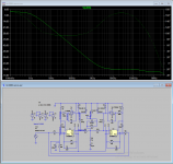
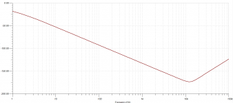
I was wondering what will be the difference between the datasheet servo implementation and multiple feedback filter architecture implementation. Attached is schematics with frequency response and phase characteristics.
Attachments
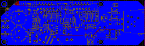
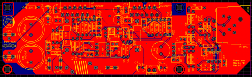
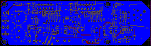
Latest revision of the PCB attached.
Includes better traces for V+ and V-
MFB servo is implemented.
Input receiver is THAT120x family of chips.
Includes better traces for V+ and V-
MFB servo is implemented.
Input receiver is THAT120x family of chips.
Attachments

Last edited:
Listening to the amp that I have built with just one LM3886 and opamp as buffer, I realized that I am not sure if I want to use THAT chips. My issue with them is that there is no THD graph available, but they state that it is 0.0005% distortion, which is pretty low. But we have LM4562 that has 0.00003% THD rating. And from what I am understanding so far (and as a result of little opamp rolling experiment) - low THD rating gives better sound.
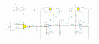
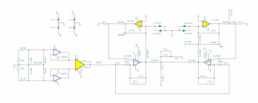
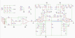
I then revised the schematics one more time with low THD chips instead of THAT chip.
I then revised the schematics one more time with low THD chips instead of THAT chip.
Attachments

I am looking at OPA2172 to use as a servo - it looks like it is very nice affordable candidate with Vos = +-0.2mV.
What other parameters would be to look for in a servo? Will the THD rating matter? What about slew rate? Open loop gain and phase vs frequency?
THD is pretty low at 0.00005%
Slew rate is 10 V/uS - should be easy to work with as faster slew rate ICs are harder to get to work stable


What other parameters would be to look for in a servo? Will the THD rating matter? What about slew rate? Open loop gain and phase vs frequency?
THD is pretty low at 0.00005%
Slew rate is 10 V/uS - should be easy to work with as faster slew rate ICs are harder to get to work stable
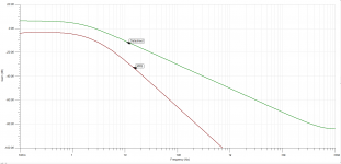
I simulated the circuit in TINA TI, but was wondering if it is going to be stable?
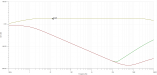
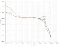
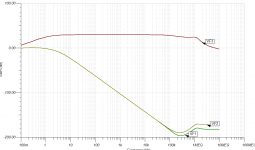
In particular, my concern is the phase response of the OPA2172 in a servo.
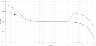
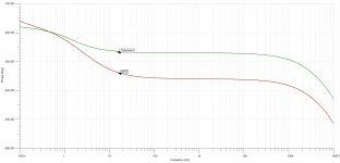
Attached is phase response with VF1 representing OPA2172 and VF2 representing OPA2134. Third line on the plot is the LM3886 at the speaker output.
Why OPA2172 has a bump there? I tried removing it, but no luck so far... Not sure what components to change or add for that.
In particular, my concern is the phase response of the OPA2172 in a servo.
Attached is phase response with VF1 representing OPA2172 and VF2 representing OPA2134. Third line on the plot is the LM3886 at the speaker output.
Why OPA2172 has a bump there? I tried removing it, but no luck so far... Not sure what components to change or add for that.
Attachments
- Home
- Amplifiers
- Chip Amps
- LM3886 in parallel with servo circuit build attempt