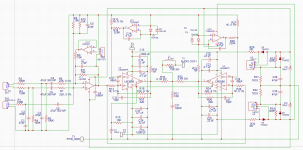
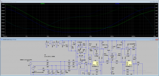
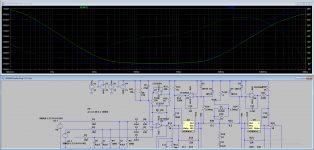
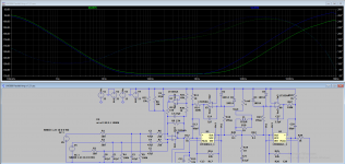
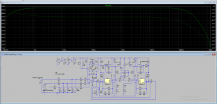
Here is the another result of adjustment for all of the filtering caps. I disconnected all of the capacitors and adjusted all values individually in the LTSpice. Then I connected all of them together to get the final picture. Freq response graph attached.

Attachments
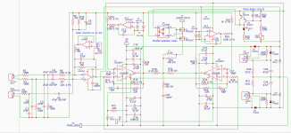
That all works. I can't see what U7 (in the sim) is trying to achieve.
You might want to think of adding a speaker relay delay because I suspect there will be some pretty big switch on thumps while the servo settles. How low you want the LF to extend is up to you but going down to near DC isn't always ideal.
You might want to think of adding a speaker relay delay because I suspect there will be some pretty big switch on thumps while the servo settles. How low you want the LF to extend is up to you but going down to near DC isn't always ideal.
Another fun part was to get servo filter values (C,R) right. I ended up with R=2M and C=1uF. Increasing resistor from 1M to 2M allowed for more linear filtering in the area of 10k and up.
Attachments
Last edited:
That all works. I can't see what U7 (in the sim) is trying to achieve.
I took this idea from the book by Douglas Self. I think that opamp is used to block negative effects related to adjusting R30,R31 that is going to be a potentiometer. I just don't know how to add variable resistor in the simulator, so I used two resistors instead. With values given, gain is adjusted from 1 to 1.62 for unbalanced input. and 1*0.68 to 1.62*0.68 for balanced input. Variable resistor is going to be 50k.
You might want to think of adding a speaker relay delay because I suspect there will be some pretty big switch on thumps while the servo settles. How low you want the LF to extend is up to you but going down to near DC isn't always ideal.
I was hoping to utilize mute circuitry for that. From what I understand, adding 100uF capacitor with 10k resistor will delay turn on for about 1 sec. I could increase that time by increasing either resistance or capacitance. I could go with 100uF and 22k to extend the time to 2.2sec... Not sure - will that work? How to discover settling time for servo?
Last edited:


I wondered if it was something like that. This is something had set up, an active volume control. Vary the ratio of P1a and P1b. I always do pots this way, there are other ways which I've never investigated tbh.
I was only able to find the gain adjustment for the way I use first opamp - that is balanced input with option for unbalanced input (just in case). I am afraid I will need to add another opamp to be able to implement active volume control. My though process behind adding gain adjustment was that I can utilize that unused second part of the opamp by just adding a few resistors and potentiometer. I am open to any other options however...
Attachments
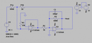
I think you would need another opamp unless you went for the basic version of the active control.
Here is a basic version and also a solid state speaker relay. P1a and P1b are the pot. Sim runs for 5 seconds, the delay is set for 2 seconds. It takes a little while to run. One possible problem (maybe Tom knows more on this) is that the LM3886 mute disables the chip output and yet the servo needs the chips output in order to derive the correction voltage. So I can foresee a switch on thump when the chip comes out of mute and the servo has to suddenly recorrect.
The opamp for the volume control needs to be one with low input bias currents (FET) to prevent wiper noise causing crackles.
U5, the PHVCv2 is a photovoltaic coupler which generates a true floating voltage source. Its like an LED and solar cell in a chip, the LED lights and the solar cell generates voltage. A floating voltage is needed for the FET gates.
If you want you can just substitute the relay with a voltage source set to about 7 volts and put it between the FET gate and source.
Attachments
I think you would need another opamp unless you went for the basic version of the active control.
Here is a basic version and also a solid state speaker relay. P1a and P1b are the pot. Sim runs for 5 seconds, the delay is set for 2 seconds. It takes a little while to run. One possible problem (maybe Tom knows more on this) is that the LM3886 mute disables the chip output and yet the servo needs the chips output in order to derive the correction voltage. So I can foresee a switch on thump when the chip comes out of mute and the servo has to suddenly recorrect.
The opamp for the volume control needs to be one with low input bias currents (FET) to prevent wiper noise causing crackles.
U5, the PHVCv2 is a photovoltaic coupler which generates a true floating voltage source. Its like an LED and solar cell in a chip, the LED lights and the solar cell generates voltage. A floating voltage is needed for the FET gates.
If you want you can just substitute the relay with a voltage source set to about 7 volts and put it between the FET gate and source.
View attachment 1035487
Looks cool. How would I get 2 sec delay for the relay?
I added relay. Will this work?
Still not sure as to how to implement the 2 sec delay for the relay? Any help will be appreciated.

Still not sure as to how to implement the 2 sec delay for the relay? Any help will be appreciated.
There are a few ways to implement a delay. I tend to like things that are well defined, however...
Here is a 555 timer version, ignore the floating ground comments as it is configured to run of an AC winding of the transformer.

For the discrete versions I would suggest you set them up as a separate simulation to begin with (and its easy to copy from one sim to another). Here are some ideas.

It is better to allow the voltage on the timing cap to have to rise significantly before it triggers the circuit (the Zener in the above circuit). Putting the cap across a B-E junction (or two junctions) means the cap only ever reaches a volt or two.
Using a FET is a good option as they have a higher turn on volts:

These use an AC input voltage to simulate switching the amp on and off quickly (no rail delay as it collapses) but you can configure to suit. The above trace shows the ripple current in the relay coil because of the rail ripple caused by a low value reservoir cap. Substitute the relay with the LED's.
Here is a 555 timer version, ignore the floating ground comments as it is configured to run of an AC winding of the transformer.
For the discrete versions I would suggest you set them up as a separate simulation to begin with (and its easy to copy from one sim to another). Here are some ideas.
It is better to allow the voltage on the timing cap to have to rise significantly before it triggers the circuit (the Zener in the above circuit). Putting the cap across a B-E junction (or two junctions) means the cap only ever reaches a volt or two.
Using a FET is a good option as they have a higher turn on volts:
These use an AC input voltage to simulate switching the amp on and off quickly (no rail delay as it collapses) but you can configure to suit. The above trace shows the ripple current in the relay coil because of the rail ripple caused by a low value reservoir cap. Substitute the relay with the LED's.
Attachments

By default, SPICE software finds the DC operating point before starting a
You can start all voltage sources at 0V by appending
.tran simulation, so the timing capacitor (C7) starts out fully charged before the simulation starts.You can start all voltage sources at 0V by appending
startup to the .tran directive. Another option is to use a PULSE() voltage source for the relay controller supply.Complex sims (and the added models make this complex) can be tricky to converge and get to run.
One trick in this case is just to make the voltage driving the 'relay' circuit dynamic. The LED drive to the coupler needed altering. An open collector output of your drive circuit pulls the LED to ground.
This works so far in...
It shows supply voltage to the relay, relay voltage and the amp output voltage.
Attachments
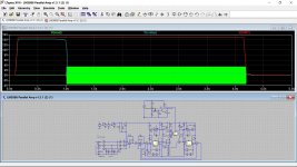
Complex sims (and the added models make this complex) can be tricky to converge and get to run.
One trick in this case is just to make the voltage driving the 'relay' circuit dynamic. The LED drive to the coupler needed altering. An open collector output of your drive circuit pulls the LED to ground.
This works so far in...
It shows supply voltage to the relay, relay voltage and the amp output voltage.
Thank you so much for help! Seems to be working now.
So, if I were to omit the protection circuitry, how much of the voltage at the output am I looking at while servo settled? I guess I'm wondering how bad those pops while turning on will be?
If I were to extend mute time - will it give servos time to settle the offset voltage? Or will the mute breaks the input-output loop that is needed for servos to start working?
I'm also thinking about making a different PCB for delay schematics and relays. This current PCB is pretty complex already.
I can't answer that one I'm afraid as I've never used the LM3886 myself. It is an unknown.
The problem I see is this...
The servo takes the output voltage of the chip and derives a correction voltage to apply at the chip input. If the servo can not correct that error while the chip is muted... and that logically would be the case because audio is not passed through the chip and as far as the chip inputs are concerned an audio signal or a correction voltage are both valid inputs... then the servo would just swing toward one rail or the other (because the loop is broken in mute) and then when the chip unmutes there would be a huge correction voltage getting applied and the results would be a very large thump as the chip unmutes.
So I think a foolproof speaker delay is needed and thinking about it more that the chip mute time should be very short. In other words the speaker delay is relied on entirely to give a silent switch on and off.
The other option is simply to design the power stages to give as low an intrinsic offset as possible and do away with an external relay. Then you would use the chips own mute delay.
- Home
- Amplifiers
- Chip Amps
- LM3886 in parallel with servo circuit build attempt