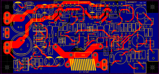
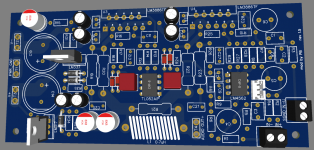
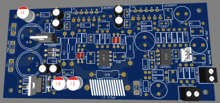
I'd clean up the pad exits in places and also avoid acid traps. Granted, in modern PCB manufacturing acid traps are not the issue they once were, but still. Why push the process unless you have to. I've marked a couple of examples below.

What happened to pin 2 of the LM3886? I know that some just cut off the pins that are marked as No Connect in the data sheet. I've never been a fan of that. I'm not a mechanical engineer, but I would think that the extra pins help reduce thermal stresses on the solder joints of the pins that you do care about.
Tom

What happened to pin 2 of the LM3886? I know that some just cut off the pins that are marked as No Connect in the data sheet. I've never been a fan of that. I'm not a mechanical engineer, but I would think that the extra pins help reduce thermal stresses on the solder joints of the pins that you do care about.
It's just one pin that I want to clip off. That will allow for really nice V- trace on both top and bottom of the PCB. On other hand, I could leave it and connect it to V- trace all together.
Connecting no-connect pins to any voltage is not recommended. There's no guarantee that the pin is not connected inside the chip. I don't think that's the case for the LM3886, but some ICs use NC pins to activate test modes and such.
You could also just use a minimum pad size and flow a pour around it.
Tom
You could also just use a minimum pad size and flow a pour around it.
Tom
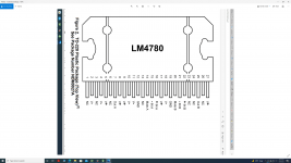
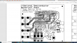
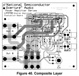
Lm4780's legs number 1 and 3 are nc , looking at the datasheet, the National/texas instruments pcb artwork shows those 2 legs connected to V+.
Gooduser , I am not a big fan of the idea of cutting the leg completely, just like Tom said, I would use a very small pad , if you connect it or not to V- , it is up to you . But to be honest , and I know I previously I recommended you to connect leg 2 to V-, maybe it is better to listen to Tom .
Tom , is necessary to have one Zobel network for each chip?
Attachments

Excellent 😊 Do you also have updated the schematic ?
Attachments
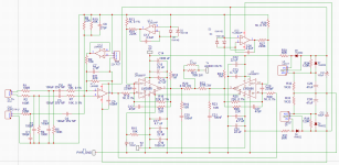
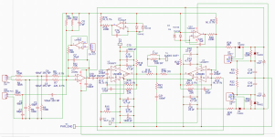
I have changed schematics to include variable gain balanced input stage from Small Signal Audio Design by Douglas Self, pg.513. In this way I can utilize another half of LM4562 opamp and add useful feature to the amp - gain adjustment. The minimum gain is -3.3dB and the maximum gain is +6.6dB. The gain with the pot wiper central is +0.2dB.
Connector is used instead of potentiometer - pin 1 and 3 are the opposite sides, and pin 2 variable pot wiper.
Rev 1.5 contains values directly from the book - since I am using unbalanced input - it's resistance would be (10K+4.7K)/2 = 7.35K
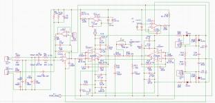
Rev 1.5.1 contains values doubled - input resistance for the unbalanced input is (22K+10K)/2 = 16K
Question - which one should I use to generate less noise?
Connector is used instead of potentiometer - pin 1 and 3 are the opposite sides, and pin 2 variable pot wiper.
Rev 1.5 contains values directly from the book - since I am using unbalanced input - it's resistance would be (10K+4.7K)/2 = 7.35K
Rev 1.5.1 contains values doubled - input resistance for the unbalanced input is (22K+10K)/2 = 16K
Question - which one should I use to generate less noise?
Attachments
Last edited:
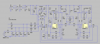
I finally got to load LM3886 model into LTSpice simulator!
Unfortunately, I think something is broken with the schematics 🙁
Sine wave at the input vs LM3886 inverted input:

Sine wave at the input vs speaker load:

Unfortunately, I think something is broken with the schematics 🙁
Sine wave at the input vs LM3886 inverted input:
Sine wave at the input vs speaker load:
Attachments


Alright, attaching bunch of files with the latest changes.
Rev 1.5.1
I added 220uF nonpolar electrolytic capacitor right after the LM4562. In simulator - at the load - it shows almost no alteration of the signal until 10Hz. I wonder if it will degrade the signal at all?
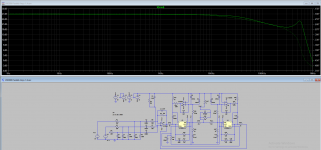
I removed one Thiele network since two were adding weird bump in the 500MHz area. Reducing capacitors in the feedback path of the LM3886 to 27pf improved on that bump further. Screenshot attached.
Input capacitors were changed to 68pf to reduce their effect on the high end frequencies.
Input nonpolar capacitors were increased to 100uF.
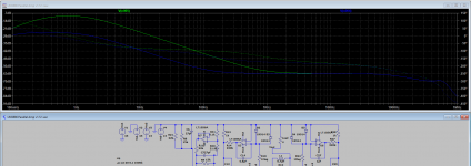
I am not sure what capacitor to use in the servo circuit. I tried 1uF and 6.8uF. Screenshot attached.
Rev 1.5.1
I added 220uF nonpolar electrolytic capacitor right after the LM4562. In simulator - at the load - it shows almost no alteration of the signal until 10Hz. I wonder if it will degrade the signal at all?
I removed one Thiele network since two were adding weird bump in the 500MHz area. Reducing capacitors in the feedback path of the LM3886 to 27pf improved on that bump further. Screenshot attached.
Input capacitors were changed to 68pf to reduce their effect on the high end frequencies.
Input nonpolar capacitors were increased to 100uF.
I am not sure what capacitor to use in the servo circuit. I tried 1uF and 6.8uF. Screenshot attached.
Attachments
-
Gerber_PCB_parallel LM3886.zip102.3 KB · Views: 94
-
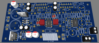
 3d-t.PNG80.4 KB · Views: 127
 -
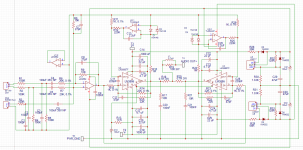
 sch-v1.5.1.PNG135.4 KB · Views: 120
 -
LM3886 Parallel Amp v1.5.1.asc11.8 KB · Views: 95
-
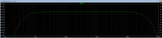 freq-responce.PNG37.5 KB · Views: 103
 -
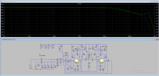 one-thiele.PNG84 KB · Views: 96
 -
 two-thiele.PNG30.4 KB · Views: 94
 -
 1uf vs 6_8uf.PNG70.8 KB · Views: 113
Last edited:


Get the time constant you want by altering the resistor rather than the cap. Its a FET opamp so no issues using high R values.I am not sure what capacitor to use in the servo circuit. I tried 1uF and 6.8uF. Screenshot attached.
Also... the servos are not now working because of the 220uF cap. Adding that cap means the LM3886 is seeing massively unbalanced input bias currents on its two inputs (1k vs 22k) and the servo output can not correct that large an error via a 220k resistor. Ideally the output of the servo opamps wants to be close to zero.
You could reduce the 220k to say 10k but then the servo is pretty much doing all the biasing rather than it just trimming out the error.
Get the time constant you want by altering the resistor rather than the cap. Its a FET opamp so no issues using high R values.
I think I will just use same 4.7uF ceramic that I use for power lines filtering next to the Lm3886 chip. They are same price as 2.2uF poly caps, but take way less space.
Also... the servos are not now working because of the 220uF cap. Adding that cap means the LM3886 is seeing massively unbalanced input bias currents on its two inputs (1k vs 22k) and the servo output can not correct that large an error via a 220k resistor. Ideally the output of the servo opamps wants to be close to zero.
You could reduce the 220k to say 10k but then the servo is pretty much doing all the biasing rather than it just trimming out the error.
I think easier will be to just get rid of that 220uF cap. I already have 100uF filtering + DC blocking at the input
- Home
- Amplifiers
- Chip Amps
- LM3886 in parallel with servo circuit build attempt