Pardon me for asking, but whats the purpose of paralleling two chips?
Did you find one not to be adequate? You need double current? Tough speaker load?
Why not three in parallel? Its been published and tested. Or six.
Or chip with extra bjt on output to boost the current.
Or just adequate discrete design.
Mostly because I have four of LM3886 lying around since my student years. Adding pair of bjt on output would be interesting idea. I might dig into that...

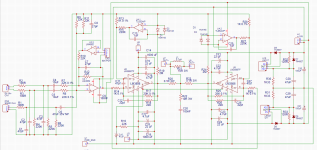
So far the progress is that I ran the amp in the simulator and fine tuned all of the capacitors and resistors' values to not affect 20Hz - 20kHz frequency response. I want to include gain adjustment at the input buffer, just because this solution is on the cover of the Small Signal Design book by D. Self 🙂 Not very practical, but I want to implement that "Self" line input lol.
As far as protection circuit - I decided I will put it on a separate PCB to dial down on the complexity.
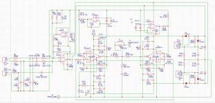
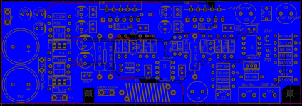
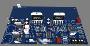
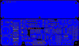
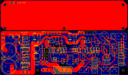
Latest schematics and PCB design attached. PCB size was changed to 50mm by 145mm.
As far as protection circuit - I decided I will put it on a separate PCB to dial down on the complexity.
Latest schematics and PCB design attached. PCB size was changed to 50mm by 145mm.
Attachments
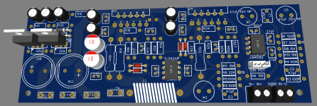

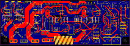
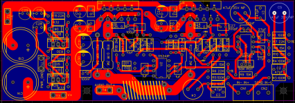
Another revision - better location for LM317 and LM337 regulators - allowed for less tracks at the bottom of the PCB.
Additionally added two soldering points for +-15V for the protection board power.
Additionally added two soldering points for +-15V for the protection board power.
Attachments
Great project, I propose the following changes
1. input capacitor foil mkp... (1 - 3u3)
2. Add speaker protection with relay
😉
Speaker protection board was discussed in separate threads:
https://www.diyaudio.com/community/threads/simple-speaker-protection-board.384572/
https://www.diyaudio.com/community/...sal-speaker-delay-using-a-triac.224957/page-4
Latest revision includes:
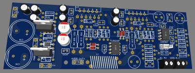
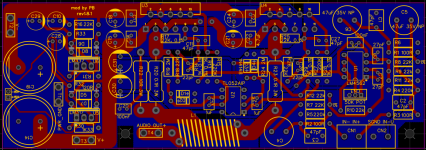
Added PCB space to mount heatsink on top of it - I already have one that is designed like that.
Added an option to install 10uF caps at the balanced input.
Adding film cap to the unbalanced input is challenging because of the low input impedance of the unbalanced input. 15uF seems to be ok, but 20uF or 22uF is the best for unbalanced input since they don't affect the frequency response that much. Adding 10uF to unbalanced input starts to affect 100Hz and lower. Verified all of that with LTspice simulation.
Gain was reduced to 20, by replacing feedback resistor from 22K to 20K
Attachments
Another thread is describing the process of designing power supply schematics and PCB for this very amplifier - https://www.diyaudio.com/community/threads/lm3886-power-supply.383496/
I will need to do some research. One video tutorial I have in mind is by John audio tech. I hope I will be able to take measurements..Excellent work !
Will you be able to measure the THD when the amp will be built ?
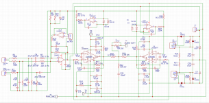
I am so intrigued by the project that I am considering building it.Updated resistors on the input stage, fine tuned stability components to be giving flat freq response from balanced and unbalanced inputs.
What function does tl052 have?
Thank You!
I am so intrigued by the project that I am considering building it.
What function does tl052 have?
Thank You!
TL052 opamps are acting as DC servos. You can find more information in this thread or TI official PDF high power lm3886 application note
I thought so too, but I preferred to ask...
Will you actually go into the built, or will it just stay with the design?
Post #128 is the final form, or there will be any edits.
I have two new TALEMA 2x25V 225W toroidal transformers ideal for this project and would like to fit it into a 2U Modushop box. 🙂
Will you actually go into the built, or will it just stay with the design?
Post #128 is the final form, or there will be any edits.
I have two new TALEMA 2x25V 225W toroidal transformers ideal for this project and would like to fit it into a 2U Modushop box. 🙂
keep in mind that if the heat sink should be mounted vertically on the PCB this will inhibit airflow.Added PCB space to mount heatsink on top of it
no problem, of course, if the pcb will be mounted vertically and the heat sink/air flow parallel to it.
I thought so too, but I preferred to ask...
Will you actually go into the built, or will it just stay with the design?
Post #128 is the final form, or there will be any edits.
I have two new TALEMA 2x25V 225W toroidal transformers ideal for this project and would like to fit it into a 2U Modushop box. 🙂
I am waiting for parts in the mail. Will progress with build hopefully soon.

Power supply board needs to be upgraded with proper rectifier bridge. I used rectifier diodes that were 3A, but you need total of 35A.
You can just use two PCBs with separate components for each channel. In that way you will have two big capacitors for each channel individually.
Yes, I'm planning full dual mono...
I would replace the originally used 1N5408 with MUR460, I think the current reserve will be sufficient,...
I just can't estimate what the charging current of the capacitors will be when switched on. (40.000 uF/per channel)
Won't I also need a softstart? 2x225w toroid + 80.000 uF 🙄
I would replace the originally used 1N5408 with MUR460, I think the current reserve will be sufficient,...
I just can't estimate what the charging current of the capacitors will be when switched on. (40.000 uF/per channel)
Won't I also need a softstart? 2x225w toroid + 80.000 uF 🙄
Black color PCB looks super cool man 😎
- Home
- Amplifiers
- Chip Amps
- LM3886 in parallel with servo circuit build attempt