....
You could verify this theory, if you drop the voltage at one leg of the dual power supply. Maybe just put 1-3 diodes in series at one side. The side with the lower supply voltage should always oscillate first. If you use a dual lab supply, just a little adjustment to try!
PS this is exactly what you get from such experiments: New questions and maybe some new answers. We call that learning. Well done FF!
Thanks to Turbowatch2 idea..
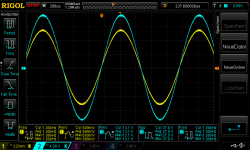
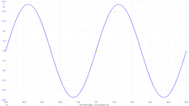
i did the following tests with 1khz sine wave. 2x 1875 ebay kit parallel, load resistive 4,459R.
pic 1 +25_-25V supply_620mVrms_start oscillating
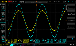
pic 2 +25_-22V supply_620mVrms_start oscillating
pic 3 +25_-22V supply_640mVrms_start oscillating
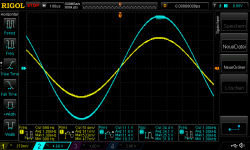
pic 4 +22_-25V supply_560mVrms_start oscillating
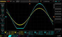
pic 5+25_-20V supply_640mVrms_start oscillating
at pic 5 the positive input goes up to 640mVrms compared to pic 1 620mVrms
chris
Attachments
-
 +25_-25V supply_620mVrms_start oscillating.png51 KB · Views: 318
 -
 +25_-22V supply_620mVrms_start oscillating.png52.2 KB · Views: 299
 -
 +25_-22V supply_640mVrms_start oscillating.png47.3 KB · Views: 305
 -
 +22_-25V supply_560mVrms_start oscillating.png47.1 KB · Views: 303
 -
 +25_-20V supply_640mVrms_start oscillating.png47.1 KB · Views: 303
Last edited:
...sorry...... i forgot to inform you that this pics are not from the same channel- this pics are from the right channel. it is a bit better before oscillating 620mVrms.
channel L give us 590mVrms. e.g. lch, post 279,post 258
channel L give us 590mVrms. e.g. lch, post 279,post 258
Compared to mine, your results look pretty excellent! 🙂
Do you think it would be possible to change your boards to inverting mode and rerun the tests?
Short the input, desolder the feedback capacitor and inject the generator signal to the lower feedback resistor?
Do you think it would be possible to change your boards to inverting mode and rerun the tests?
Short the input, desolder the feedback capacitor and inject the generator signal to the lower feedback resistor?

It's the 22uF, 16V NP capacitor. You have the inverting input right there, ground and everything.
I tested with +/-25 voltages. I have similar oscillations on the positive channel, close to clipping, exactly as you have. I am not too worried about that.
I tested with +/-25 voltages. I have similar oscillations on the positive channel, close to clipping, exactly as you have. I am not too worried about that.
It's the 22uF, 16V NP capacitor. You have the inverting input right there, ground and everything.
I tested with +/-25 voltages. I have similar oscillations on the positive channel, close to clipping, exactly as you have. I am not too worried about that.
Hi
me too. i think about a "limiter LED / clipping indicator" at the output of one channel. to be save e.g. at 580Vrms input --> 12,5Vrms at the output.
LED= 15mA , Uled 2V ......Rv = U/I = 10,5V/0,015A = 700R --> 680R🙂
chris
EURECA!
Increasing the gain in the 1875 solves the oscillation. This is with -3,33x.
I need to come up with optimum values for the gain and compensation now...
20kHz, just before clipping attached.
EUREKA!!!! You do serious work in the bathtub such as Archimedes did? Or was it in the sauna before the cold dip
 you got the idea?
Anyway, with my suggested 3.5 times (minus/inverting) I'm in the lucky zone. Old saying: not even the best planning and systematic approach can replace undeserved luck.
As long as you measure THD at 1W/8Ohm, you need less that 2 times LM1875 gain because the OP-AMP operates below the sudden and steep raise in THD. I suggest that you test yourself at which amplitude the NE5534 THD starts raising fast (I found no such datasheet information) and that you stay below this raising level until the LM1875 clipping point.
Very useful and systematic work. We all benefit from the results of your efforts.

I don't think these two oscillations were related.
When coming closer to the negative clipping, begun to show a similar new oscillation as on the positive rail, only superimposed to the oscillation which had already started from -12V.
Anyways, sauna time later today, and then its
time...
When coming closer to the negative clipping, begun to show a similar new oscillation as on the positive rail, only superimposed to the oscillation which had already started from -12V.
Anyways, sauna time later today, and then its
I am back at the -1.5x (only) gain at the 1875.
I have found out an interesting phenomenon.
Increasing the gain at the high frequencies begins to cancel the - lets call it: "half rail oscillation".
There seems to be several ways to cancel out this oscillation.
Increasing the over all gain at the 1875, ruins the THD, well not completely, but some here and some there and soon you have nothing... But cancels some (- all) of the oscillation.
But increasing the gain at HF only, also improves the THD at lower frequencies!
I can increase the HF gain both at the 5534 and at the 1875 and both helps to the half rail oscillation problem.
Interesting...
Top rail oscillation, near (at) clipping, will always be there, so lets forget that. It is built into the chip for good.
Last edited:
As the half rail oscillation happens at the "half rail", of course cranking up the PSU voltages moves it further away...
It seems that it is quite difficult to filter it out completely, without loosing all the good THD we have gained with our topology already.
And we get the top wave oscillation anyway...
Although in theory at 1kHz/1W/8R we are now down at 0.00005%, yes, thats 5 zeros. But it rises very quickly as the frequency goes up, with the filtering we must have. At 20kHz 0.05%(?) need to measure it though, to be sure.
So? Maybe full +/-30V rails to the 1875 and limit the output voltage swing with the opamp? Opamp must clip first.
Here you can see an other good reason for this... 1875 clipping... With its top rail oscillations, which the opamp then tries to fix...
Attachments

.
..........................................................
With the LM3886 there seems to be an easy test to find a real one: Just short the output while running some sinus signal into a resistor. The fake one will be dead, the real TI chip does not care.
Did anyone do this test with "your" LM1875? As far as I have read, the current limiter seems to work in some of your builds, which is not the case with the fake 3886.
As this part of the chips seems to be a problem in constructing fake China chips, I would like to share my ideas with you, as it might help.
..................................................................
I finally decided to move-on with my “triple” and my LM1875 test-amp had become redundant.
So, I did the short-circuit test as suggested.
Checked first that the amplifier still worked well with the oscilloscope and a sine-wave signal – OK.
With power off, I reduced the input signal to very little and short-circuited the load. Turning on the power did not harm the LM1875.
After having turned the power off again, I removed the short-circuit. Then, I put power on and adjusted the input level to 10Vpp at the output. Power off again and the short-circuit back across the load.
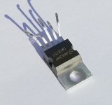
When I turned power on, I heard a small “paff” from the LM1875 so I switched power off and removed the short circuit. When I switched power on again, I heard two more loud “paff”-”paff”. The output voltage would remain at around -12V constantly. The LM1875 chip was destroyed. I removed the chip from the PCB and measured 250 Ohm between output and the negative power terminal without supply voltage. Also my LM1875, that performed like a genuine LM1875 dynamically, had a useless current limiter. Performance-wise it was “fake”.
The photos show the defect LM1875 IC after test. No signs of physical defects – I wonder how the “paff”s are produced? The external componenets were in functional order.
As Turbowatch2 rightfully says, there are differences between geniune and fake.
Genuine LM1875s cost a little more than half of genuine LM3886s. One LM3886 has a power capacity a little above four LM1875s. As the fakes are performing dynamically close to genuine LM1875, I will continue with fakes during the experimental phase. If a PCB is later on made, I may consider genuine LM1875s for that.
Attachments
Last edited:
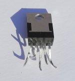
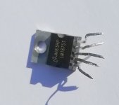
FauxFrench .., of course i recognise your "LM1875" chip 🙁,
I am using the same ones. However when building and testing my amp recently, i came to the conclusion, it rather behaved as a TDA2050.
The chip clearly did not appreciate voltages above 24 V and just under 25 V a kind of protection circuit was probably triggered, resulting in oscillatory artifacts on the output. Reducing the voltage to under 24 V restored the stability.
Of course the +/-30 V of the LM1875 specification was clearly not met.
And i did not perform your "ultimate" test.
I was somewhat intrigued by this behaviour and out of curiosity i ordered some chinese TDA2050's. Of course fake TDA2050's because the genuine ones were taken out of production years ago.
When i received the copies my assumption was confirmed, the look and performance was identical.
However the chips as such are doing a decent job, more or less in line with the TDA2050 datasheet.
And as such the TDA2050 also "was" a decent chip.
Again out of curiosity i ordered 4pcs of UTC's "genuine" TDA2050. Apparently UTC is manufacturing the chip under license and at least a professional looking datasheet of the UTC chip is available. (Chip ordered and supplied by Reichelt).
From what Google found, this chip is in current production and the closest to the original one. It is also claimed to be short circuit proof.
In the coming days i will perform some tests and measurements of the various chips (LM1875 and TDA2050) in my possession and post the results.
Well.. this is just my story and please be aware that your "exploded LM1875" is also sold by the Chinese as "TDA2050".
Fred
Last edited:
I assume I will be scoffed at but I stumbled upon these boards and thought they might be interesting.
Free ship 2PCS GC1875T parallel version LM1875 power amplifier PCB power amplifier PCB-in Amplifier from Consumer Electronics on AliExpress
Free ship 2PCS GC1875T parallel version LM1875 power amplifier PCB power amplifier PCB-in Amplifier from Consumer Electronics on AliExpress
Hi
please look at the other thread-some details are done there too.
shortcut test:
https://www.diyaudio.com/forums/chip-amps/341675-ebay-mono-lm1875-kit-16.html#post5918960
performance of "fake" chip:
https://www.diyaudio.com/forums/chip-amps/341675-ebay-mono-lm1875-kit-11.html#post5910381
chris
please look at the other thread-some details are done there too.
shortcut test:
https://www.diyaudio.com/forums/chip-amps/341675-ebay-mono-lm1875-kit-16.html#post5918960
performance of "fake" chip:
https://www.diyaudio.com/forums/chip-amps/341675-ebay-mono-lm1875-kit-11.html#post5910381
chris
Let's make the input stage (opamp stage) and paralleled output stage PCBs separate?
We can fool around with different configurations then?
The paralleled output board should have possibility to both inverting and non-inverting input.
We need 3-wire connection between the boards: GND, input and FB from its output.
Input is 2 pins as both inverting and non-inv is needed. So 4-pin connector...
?
Edit:
I suggest we parallel four LM1875s.
Copy the offset control from BPA200 and use a 4ch opamp for it.
Last edited:
Hi
i am behind the schedule of amp building and of course the composite amp. i remember that FF wrote that it make sense to use an opamp for each LM1875 - so your board looks fine for me.
chris
i am behind the schedule of amp building and of course the composite amp. i remember that FF wrote that it make sense to use an opamp for each LM1875 - so your board looks fine for me.
chris
FauxFrench .., of course i recognise your "LM1875" chip 🙁,
I am using the same ones. However when building and testing my amp recently, i came to the conclusion, it rather behaved as a TDA2050.
The chip clearly did not appreciate voltages above 24 V and just under 25 V a kind of protection circuit was probably triggered, resulting in oscillatory artifacts on the output. Reducing the voltage to under 24 V restored the stability.
Of course the +/-30 V of the LM1875 specification was clearly not met.
And i did not perform your "ultimate" test.
I was somewhat intrigued by this behaviour and out of curiosity i ordered some chinese TDA2050's. Of course fake TDA2050's because the genuine ones were taken out of production years ago.
When i received the copies my assumption was confirmed, the look and performance was identical.
However the chips as such are doing a decent job, more or less in line with the TDA2050 datasheet.
And as such the TDA2050 also "was" a decent chip.
Again out of curiosity i ordered 4pcs of UTC's "genuine" TDA2050. Apparently UTC is manufacturing the chip under license and at least a professional looking datasheet of the UTC chip is available. (Chip ordered and supplied by Reichelt).
From what Google found, this chip is in current production and the closest to the original one. It is also claimed to be short circuit proof.
In the coming days i will perform some tests and measurements of the various chips (LM1875 and TDA2050) in my possession and post the results.
Well.. this is just my story and please be aware that your "exploded LM1875" is also sold by the Chinese as "TDA2050".
Fred
Hi Fred,
Many thanks for sharing your experience with LM1875/TDA2050.
As a long time collector for amplifier projects I never had time to implement, I have TDA2005, TDA2030, TDA2040, TDA2050, TDA2051 (to my surprise) and LM1875. Except for the TDA2005, they are pin compatible. Some are from the "good old days", some recovered from commercial units and some bought at such good prices that they may be fake.
On the fakes I will still add that some seem to perform close to genuine LM1875 as long as the short-circuit test is avoided. I even managed to take some to 29.5V supply without damage. For me, they can still be used for experimental work or audiophile use as long as the output is not short-circuited. It is not that they are worthless. I used two TDA2050 in an amplifier and they sounded fine as well. Only at high sound level and with heavy bass, I sometimes heard some click-sounds that could correspond to current-limiter interference.
It may be that you are right that we can decide if we want LM1875 or TDA2050 (perhaps also TDA2051) to be printed on the IC, we anyway get the same chip.
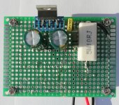
I have now made a small LM1875/TDA2050 tester such that I can do basic tests on all my chips before soldering them in a circuit. I will show my test results when ready.
UTC2050 will most likely work as well as "old" TDA2050. They are not fools out there and perhaps they even worked as second source to STMicroelectronics in those days.
Attachments
Last edited:
Hi
i am behind the schedule of amp building and of course the composite amp. i remember that FF wrote that it make sense to use an opamp for each LM1875 - so your board looks fine for me.
chris
Hi Chris,
When commenting on the composite amplifier article I believe having said that using an OP-AMP for each individual LM1875 was hardly worth it. My expectation is one OP-AMP for a parallel group of LM1875s. That means, two OP-AMPs for a single channel with BTL-configuration. One OP-AMP not inverting the input signal and one inverting the input signal.
- Home
- Amplifiers
- Chip Amps
- LM1875 in parallel configuration and used in a composite amplifier.