...1875 ruled out. Identical behaviour with the new one.
Also a possibility of a PCB issue ruled out (offset adjustment in close proximity of the negative rail) - no effect.
Next is around the 5534?
I'll be back...
Also a possibility of a PCB issue ruled out (offset adjustment in close proximity of the negative rail) - no effect.
Next is around the 5534?
I'll be back...
...1875 ruled out. Identical behaviour with the new one.
Also a possibility of a PCB issue ruled out (offset adjustment in close proximity of the negative rail) - no effect.
Next is around the 5534?
I'll be back...
I recall having read sometime ago and somewhere on this forum a VIP state that a problem with class AB is that the stability changes dynamically with the exact output voltage. I interpreted this such that with momentarily higher output voltage, the currents running in the output transistors and in the driver transistors is higher, due to the higher load current, and that a higher current level changes the loop gain, which causes the amplifier to be unstable only from that output level. At least to me it sounds plausible and matches with some earlier LM1875 experience.
Another possibility is that the current limiter in some way starts disturbing the loop.
In both cases, it is a chip-inherent characteristic we cannot do much about except for not loading each LM1875 with too much current.
Begins to look like that, yes.
I slowed down the 5534 a lot (compensation 22pF, instead of 10pF), but still the same behaviour.
I have only one more thing left to try; change the 5534, to rule that out.
Also, if someone could test the 1875 in inverted mode close to clipping with different negative gains and different loads? That could be usefull information.
With an authentic chip of course...
I am leaning towards the idea, that this is a 1875 related feature?
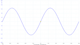
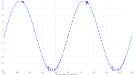
Here is results if rail voltages are lowered to +/-24V.
With +/-25V we would get quite clean 25W output.
Anyways, 20kHz 8R...
Positive rail clipping. Otherwise positive rail is clean.
Negative rail starts to oscillate shortly after -12V.
But much less oscillations when rail voltages down.
I can also see some crossover distortion.
Compensation 10pF.
Attachments
I just found my previous but "fake" 😱 results from 2018 experiments:
With 16 Ohm loads, I can take the amplifiers to +/-29.5V without clipping. With 8 Ohm loads, the self-oscillation phenomenon is only observed for supply voltages from +/-25V and above. With 4 Ohm loads, self-oscillation is avoided with supply voltages below +/-18V.
Though fake, my results may be pretty consistent with yours. I recall my LM1875 gain at that time to be around 12. Higher gain did not remove the problem.
So you practical guys come to the same conclusion that my theoretical view on it delivered. It may be in the chips construction. Note: "Nothing is more practical than a good theory".
My conclusion was based on the following:
With such complementary amps there is always some kind of paradox situation, when the clipping level is reached. You have to drive the final stage with a voltage a little higher (around 0.3 -2 volt) than the maximum output voltage to compensate for the voltage drop the transistors have from collector to emitter.
So, if the driver stage is driven by the same voltage, because of the other diode drops any transistor has, you will always run into some stability issues, near clipping. This is due to Uce. The often used Darlington-transistor configuration makes things even worse.
Some "Real", perfect A and A/B amplifiers and many PA-amps (they are run into clipping quite often!) do not have this problem, because you run the driver stage 4-10 volts higher than the power transistors feed. These amps clip, if done right, just perfect. The sinus gets chopped of, that´s all. You need a good, "hard" power supply, too. Expensive to build.
You need a transformer with 4 (two extra) output voltages or a second, small transformer, that often "float´s " on the power transformer. I once wound a few extra rounds of thin wire on an torodial transformer, which gave an extra +-3 volt over the stock output AC to get the extra supply. Needs own rectifier and capacitors, better a (floating)regulator, too.
These little amp-chip amps usually have no provision for a separate driver voltage, as they are low cost devices, often even powered by batteries.
You could verify this theory, if you drop the voltage at one leg of the dual power supply. Maybe just put 1-3 diodes in series at one side. The side with the lower supply voltage should always oscillate first. If you use a dual lab supply, just a little adjustment to try!
PS this is exactly what you get from such experiments: New questions and maybe some new answers. We call that learning. Well done FF!
Last edited:
Not to worry.
As long as removing the load fixes everything, we just need to find how many 1875s we need to parallel, to keep away from trouble.
As long as removing the load fixes everything, we just need to find how many 1875s we need to parallel, to keep away from trouble.
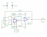
Compensation at the 1875 feedback improves things a lot.
100pF parallel with the Rf1.
Rf1=2k2, Ri1=1k5.
I have the non-inverting input of the chip directly grounded. That results in offset at the chips output. Which 5534 will fix. I was wonderin, if I put 1k in series, with the non-inv, to gnd?
I have the oscillation problem at the negative channel. Everyone else seems to have it at the positive ch?
And the only difference is the inverted configuration in my circuit???
Just wondering...?
Edit:
Signal is 20kHz.
Attachments
Last edited:
Not to worry.
As long as removing the load fixes everything, we just need to find how many 1875s we need to parallel, to keep away from trouble.
I'd second that. The explanation by Turbowatch sounds reasonable. Apart from that there's basically not much left to do than either moving on or putting all efforts to rest.
Which 5534 will fix. I was wonderin, if I put 1k in series, with the non-inv, to gnd?
Try it.
I have the oscillation problem at the negative channel. Everyone else seems to have it at the positive ch?
Did you try the slight supply voltage imbalance that was suggested? Give the amp like 2V more on the negative rail, or reduce the positive rail by 2V and see if that shifts the oscillations to the other rail.
Did you make any THD measurements yet? How does it compare to a simple inverting LM with low gain?
And could you share an FFT plot of such a measurement, say with 1meg FFT and like 10 seconds averaging? I'm interested in the performance of your PicoScope and think about getting one myself.
I don't think the 1.8K at in+ is a good idea; From the datasheet Ios = 0 typical means it is internally compensated.
http://www.ti.com/lit/pdf/snas524
The datasheet states an Input Offset Current of Typical 0uA, with +-0.5uA being the limit. But it also states an Input Bias Current of +-0.2uA within a tested limit of +-2uA.
From a google result:
The input offset current (IOS) is equal to the difference between the input bias current at the non-inverting terminal (IB+) minus the input bias current at the inverting (IB-) terminal of the amplifier. Offset current is typically an order of magnitude less than bias current.
From this I would deduce that a resistance at the non-inverting input, that equals the resistance at the inverting input, would be a necessity to cancel out the bias currents of both inputs and thus arrive at the stated offset current of 0uA. Can't hurt to try it out in any case.
Will try the 1k resistor.
Did not try the supply imbalance - yet.
Haven't done that yet. I want to fix the oscillation first. But I know a simple inverting LM is not much better than a non-inverting. Only less noisy.
The scope is not ideal for THD (audio), do not buy it just for that. You need more bits than 16. And you still need even the calculator to deduct the loopback THD.
A high performance soundcard is much better!
The nerds on the nerd forum here at diyaudio are coding a software; "Diana". Check that. That will automate the loopback THD deduction part.
I am not using it yet. I can calculate myself. 🙂
Did not try the supply imbalance - yet.
Did you make any THD measurements yet? How does it compare to a simple inverting LM with low gain?
And could you share an FFT plot of such a measurement, say with 1meg FFT and like 10 seconds averaging? I'm interested in the performance of your PicoScope and think about getting one myself.
Haven't done that yet. I want to fix the oscillation first. But I know a simple inverting LM is not much better than a non-inverting. Only less noisy.
The scope is not ideal for THD (audio), do not buy it just for that. You need more bits than 16. And you still need even the calculator to deduct the loopback THD.
A high performance soundcard is much better!
The nerds on the nerd forum here at diyaudio are coding a software; "Diana". Check that. That will automate the loopback THD deduction part.
I am not using it yet. I can calculate myself. 🙂
The scope is not ideal for THD (audio), do not buy it just for that. You need more bits than 16. And you still need even the calculator to deduct the loopback THD.
A high performance soundcard is much better!
I know that it is not ideal, but maybe it is sufficient. I have seen a plot showing a noise floor of -130dBu, which is about 20dB worse than what my soundcard can do. Not sure about the input range though - I've also seen -160dB from the 4262, but with +-10mV input range. The advantage is a flat response beyond 100kHz (most soundcards show a rising noise floor above 30kHz), and, obviously, the DC coupling and thus the more versatile lab use compared to a QA401 or a soundcard. Think about it this way: If I can manage to build something that has such a low THD that it is indiscernible from the spurs I can see on a loopback test, then why should I bother to know how low the actual THD is? It's already low enough by then. And there are things like notch filters, which will help getting the most out of 16 bits.
The nerds on the nerd forum here at diyaudio are coding a software; "Diana". Check that.
Wanted to, but Edmund didn't tell me the password yet 🙁.
Wanted to, but Edmund didn't tell me the password yet 🙁.
Password is no secret:
Yohimbine
Will try the 1k resistor.
Nope. Thats not it.
Might as well have it on the gnd, with less noise.
Password is no secret:
Yohimbine
For me at least it was. Thank you.
Nope. Thats not it.
Might as well have it on the gnd, with less noise.
Interesting. Maybe a small offset on the NE-output?
Maybe a small offset on the NE-output?
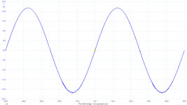
No change.
Also railvoltage imbalance, no change.
To me it looks like the 1875 starts to go mad first.
5534 tries to talk reason to it, but the idiot 1875 wont listen...
Attachments
Do you have a FET input opamp handy, like a TL071 or better? Won't help with oscillations, but maybe fix the offset problem.
Do you have a FET input opamp handy, like a TL071 or better? Won't help with oscillations, but maybe fix the offset problem.
I believe I have. Although the offset is adjustable in my proto...
For rolling different opamps I need to prepare a new proto.
I am also runing out of 1875's.
So, if someone has too many authentic samples laying around and wants to get rid of some,
throw me with a PM.
Maybe we can work something out?
I have extra proto-PCBs, for example, to throw back... Or something...
On page 6 of the LM1875 datasheet, a schematic of the LM1875 design is shown. The output stage is not complementary but NPN's. Could that be the reason for the asymmetrical oscillation phenomenon when the output stage design is asymmetrical as well?
I actually have fine oscillations both on the positive and negative tops but only very near to clipping. My clipping is not fully symmetrical either. I know that with my "fakes", the basis for absolute conclusions is doubtful.
Very good and systematical work palstanturhin!
I actually have fine oscillations both on the positive and negative tops but only very near to clipping. My clipping is not fully symmetrical either. I know that with my "fakes", the basis for absolute conclusions is doubtful.
Very good and systematical work palstanturhin!
- Home
- Amplifiers
- Chip Amps
- LM1875 in parallel configuration and used in a composite amplifier.