Let's make the input stage (opamp stage) and paralleled output stage PCBs separate?
We can fool around with different configurations then?
The paralleled output board should have possibility to both inverting and non-inverting input.
We need 3-wire connection between the boards: GND, input and FB from its output.
Input is 2 pins as both inverting and non-inv is needed. So 4-pin connector...?
Edit:
I suggest we parallel four LM1875s.
Copy the offset control from BPA200 and use a 4ch opamp for it.
You may be right that four LM1875 are needed to ensure no oscillation. I believe our present work with LM1875 has disclosed many important aspects of parallel coupling of power amplifier chips. And, revealed details of the LM1875 behavior that is valuable for LM1875 work in the future.
In a previous posting of mine, I stated that one LM3886 could be compared to four LM1875. This is not correct as I forgot that the LM3886 IC is only single channel. One LM3886 can almost perform as three LM1875.
If we assume that we use four LM1875 in parallel, we need eight LM1875 for one BTL-configured channel. That can be done for initial tests. For a more permanent implementation in the end, I find it valid to reconsider if LM1875 is still the best choice. An implementation with LM3886 or even LM1876, genuine quality, is less costly and perhaps more future-proof as I guess the genuine manufacture of LM1875 may soon terminate.
Working with separate power boards and control board in a modular structure is practical but each board has to be compact such that they can be placed close to one another or I fear we might have oscillation problems. I have started preparing a Vero-board with three LM1875 power "cells" that are located next to one another. I do not have room for four cells. I also have room for the controlling OP-AMP.
Hi Chris,
When commenting on the composite amplifier article I believe having said that using an OP-AMP for each individual LM1875 was hardly worth it. My expectation is one OP-AMP for a parallel group of LM1875s. That means, two OP-AMPs for a single channel with BTL-configuration. One OP-AMP not inverting the input signal and one inverting the input signal.
sorry...my fault..
actually i use the nice weather to go cycling the last days...🙄🙂
.....I have started preparing a Vero-board with three LM1875 power "cells" that are located next to one another.
fine FF
😎
fine FF
😎
Nice weather in the winter -> use the opportunity to go out with the kids. Amplifier technology does not evolve so fast that you cannot take off for even a week.
Anyway, I used my new LM1875 test-jig to analyze my inventory of LM1875/TDA2050/TDA2051. I actually got some consistent results.
+/-24-25Vdc supply voltage, sine-wave and square-wave test signals until clipping, 3.5 times gain, inverting configuration, Zoebel-network adapted for LM1875, 10 Ohm load:
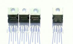
All items passed without damage but some specimens did not perform well. Those that performed correct are shown on the first picture and were three batches of LM1875 with writing in beige and some TDA2051 items. No oscillation except for at the very peaks during clipping.
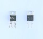
Those that did not perform well are shown on the second picture and include one batch of LM1875 with marking in white and a batch of TDA2050. The LM1875 would start oscillating near the peaks but before clipping. The TDA2050 would oscillate, with a square-wave, in the negative half-period around 40% of the supply voltage but higher up it would stop.
The well performing specimens probably perform similar to the one in my test amplifier. The LM1875 and TDA2051 showed very similar behavior.
For those items that did not perform well, I increased the gain to almost 20. It is unfair to criticize a performance when the item is clearly used outside of what is specified as safe operation. This increase in gain made the LM1875s, with marking in white, perform perfectly well. Thus, within the gain-range advised, also they function. The TDA2050s still showed the instability at certain output voltage levels.
Adapting the Zobel-network values to those recommended for TDA2050 did not change much.
Then, I changed the power supply for one with +/- 18Vdc. All TDA2050 specimens following performed well. The TDA2050 datasheet specifies the same absolute maximum supply voltage as highest operational supply voltage. The TDA2050 did actually survive the +/-24-25Vdc supply voltage but became partly unstable. From my recent experience I would not use more than +/-20-22Vdc even for genuine specimens.
fdenys impression that they are all the same chip is in many cases supported by my tests. But, there are also batches that consistently deviate in behavior from other batches. In only one case, I tested the output current limiter and that was fatal for the chip. Most likely, a similar short-circuit test of the items mentioned here would also have destroyed a large number of my test items.
Anyway, I used my new LM1875 test-jig to analyze my inventory of LM1875/TDA2050/TDA2051. I actually got some consistent results.
+/-24-25Vdc supply voltage, sine-wave and square-wave test signals until clipping, 3.5 times gain, inverting configuration, Zoebel-network adapted for LM1875, 10 Ohm load:
All items passed without damage but some specimens did not perform well. Those that performed correct are shown on the first picture and were three batches of LM1875 with writing in beige and some TDA2051 items. No oscillation except for at the very peaks during clipping.
Those that did not perform well are shown on the second picture and include one batch of LM1875 with marking in white and a batch of TDA2050. The LM1875 would start oscillating near the peaks but before clipping. The TDA2050 would oscillate, with a square-wave, in the negative half-period around 40% of the supply voltage but higher up it would stop.
The well performing specimens probably perform similar to the one in my test amplifier. The LM1875 and TDA2051 showed very similar behavior.
For those items that did not perform well, I increased the gain to almost 20. It is unfair to criticize a performance when the item is clearly used outside of what is specified as safe operation. This increase in gain made the LM1875s, with marking in white, perform perfectly well. Thus, within the gain-range advised, also they function. The TDA2050s still showed the instability at certain output voltage levels.
Adapting the Zobel-network values to those recommended for TDA2050 did not change much.
Then, I changed the power supply for one with +/- 18Vdc. All TDA2050 specimens following performed well. The TDA2050 datasheet specifies the same absolute maximum supply voltage as highest operational supply voltage. The TDA2050 did actually survive the +/-24-25Vdc supply voltage but became partly unstable. From my recent experience I would not use more than +/-20-22Vdc even for genuine specimens.
fdenys impression that they are all the same chip is in many cases supported by my tests. But, there are also batches that consistently deviate in behavior from other batches. In only one case, I tested the output current limiter and that was fatal for the chip. Most likely, a similar short-circuit test of the items mentioned here would also have destroyed a large number of my test items.
Attachments
Last edited:
Thanks FauxFrench, i can confirm that your non-performing fake-TDA2050's are to be avoided. They are relatively worthless unless you need about 15W max.
I suspect they are probably fake TDA2030's. (As you mentioned they are performing well at +-18V). Unfortunately i have 10 of them laying around. 😡
Your report is actually saving me time since all common "fakes" (supplied presently) are covered in your posting.
The only chip missing yet is probably the "UTC TDA2050V".
So it will be my pleasure to do this tomorrow. For this chip i am also intending to do a short- circuit test. If the results are encouraging i myself tend to go for these ones.
Or one of the well performing "fake" LM1875's of your report.
Still better of course if i can finally find unsuspected-genuine LM1875s ...
Fred
Last edited:
has somebody measured the quiescent current of these chipamps?
the genuine tda2050 and lm1875 draw around 50mA.......see datasheet.
the genuine tda2050 and lm1875 draw around 50mA.......see datasheet.
UTC TDA2050L quick test
Yesterday FauxFrench posted a very useful overview of the most common of "LM1875- alike's" (fakes) in his possession. Including practical tips and selection recommendations.
In this survey the UTC TDA2050 also deserves a place. The chip is in current production and the manufacturer is a taiwanese enterprise Unisonic/UTC.
I understand they obtained a license for the chip after ST took it out of their range, years ago.
I had a few copies laying around (supplied by Reichelt) so today i performed some measurements.
A professional datasheet is available - as it should, It shows UTC is to be considered a professional and serious company.
I tested the chip in a non-inverting configuration (to enable a 1:1 comparison with an identical amplifier in my possession).
(have not tested stabilty at low gain)
I started to look for its max output of clean power at 8 Ohm. When increasing the Supply voltages to +- 25V (the max permissible re datasheet) i measured about 32W of clean power, just before clipping. However that lasted only a short while..!
Pretty soon a thermal and/or voltage protection circuit was throttling down the chip. At 8 Ohm i had approx 15.9V but to my surprise it was adjusted downwards to approx 8V RMS and a funny waveform. (It looked like the pos. supply was switched off).
However no oscillatory artefacts on the output as i had on the "LM1875" near clipping.
After further tests it became clear:
Apparently the chip has effective thermal- and over voltage protections built in.
It starts to be triggered just over 24V.
Conclusion do not power this chip over max 23.5V.
The datasheet consistently refers to 22V supply at 8 Ohms.
At 23.5V voltage i obtained about 14.7 RMS /8Ohms (27W) and no throttling.
Then i applied the "ultimate" test. I shorted the LS-output to ground (with about 10V RMS sinus output) On the scope the sinus came right back after the short-circuit condition was taken away.
This chip has effective protection circuitry built-in!
Offset voltage at output was excellent - about 2 mV (However at switching on/off i noticed much higher values)
Regarding mjf question of yesterday: i measured a quiescent current of about 30 mA (Vc+)
Next i did some quick listening tests (one channel UTC, other channel FauxFrench report, second left chip).
Sounds excellent, probably somewhat extended bass. (Note i used 220uF caps iso 100uF- in compliance to the datasheet. Also adapted the Thiele network)
However, and i am somewhat puzzled -why??-: the TDA2050 becomes hotter in normal use. Up to 10 degrees hotter i was used to. And i have not yet tested for extended listening periods. The Thiele resistor measured 48 degrees.
But do not see oscillatory behaviour on the scope. Also this channel is dead silent with ear on the speaker. need to further investigate this heating issue.
That in a nutshell are my first findings..
I don't know..it's probably advantageous to have effective protection circuitry on board but the throttling down experience was rather annoying.
So is the additional heating issue.
The fake LM1875t issue in general is a major annoyance and i had hoped the UTC chip was the solution, but it has its own irritations.
I probably prefer the fake LM1875t.
Fred
Hi Fred
Thank you for doing this detailed test. It is interesting that some chip (UTC) are working after shorted outputs!! my fake LM1875 from the ebay/ali mono kit are not working after shortcut tests - i got a high current and my lab psu goes into cc mode.
https://www.diyaudio.com/forums/chip-amps/341675-ebay-mono-lm1875-kit-16.html#post5918960
i think that the lower voltage rating is mentioned in "john audio tests" with this chips and he showed the smaller die- he opened/show a picture of and open chips inside.
chris
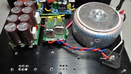
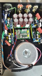
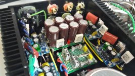
...small step forward with my 2x1875 paralleing amp...
Hi
i go ahead with my amp (2x1875parallel), soldering cabling is a nightmare.
primary fuse is according to the datasheet (transformer 120VA Sedlbauer) 0,8A T
secondary 2x 4AT fuse the small board left beside the trani. under this board the +V/GND/-V goes under the pcb to the cap bank. voltages are all ok = 26,75 -26,80V DC each rail.
open:
connection cap bank to amp boards
input connection
output cabling
special 😀 - under the LM1875 i drilled 6 holes for better "cooling" 😀
if you have comments they are very welcome..😉
chris
Attachments
is the quiescent current of the "fake lm1875" lower as the one of the tda2050?
Have not measured the "fake" lm1874 current, will do that tomorrow.
Why is the quiescent current an issue for you?
if you have comments they are very welcome..😉
I'd put the secondary fuses behind the capacitor bank. The charging currents will be too much for the fuses in the long run and weaken them, probably leading to blowing much too soon and somewhat "unexpected" during listening or on power-up.
I'd put the secondary fuses behind the capacitor bank. The charging currents will be too much for the fuses in the long run and weaken them, probably leading to blowing much too soon and somewhat "unexpected" during listening or on power-up.
thanks preamp
the fuse between cap bank and amp board is really tricky because .....sometimes i hate me for choosing such a small housing 😀 - .....i have no space inside🙄😱🙄
Yesterday FauxFrench posted a very useful overview of the most common of "LM1875- alike's" (fakes) in his possession. Including practical tips and selection recommendations.
In this survey the UTC TDA2050 also deserves a place. The chip is in current production and the manufacturer is a taiwanese enterprise Unisonic/UTC.
...................................................................
Fred, once more an excellent report. This time on the UTC-TDA2050.
I can follow all in the report except the conclusion. I will elaborate.
The UTC-TDA2050 is a well sounding, reliable/predictable, temperature and over-current protected chip. Checking at Reichelt it cost 1Eur/pcs, which is about 1/3rd of the cost of LM1875 (genuine). The quiescent current of UTC-TDA2050 is at least not above that of LM1875 so the increased heating I do not understand either.
The annoying problem with fake LM1875s is that we never know what is going to be delivered. Some have close to genuine LM1875 dynamic performance, some have significantly worse dynamic performance, some may have over-current protection but most do not (at least non-functional). If you are aware of the draw-backs of fake LM1875s and know how to compensate for their weaknesses, you can make them perform well but performance remains batch individual.
My guess is that the SQ of LM1875 (genuine) and UTC-TDA2050 is so close that it is not a major issue which one is used.
The difference, apart from the price, between LM1875 and UTC-TDA2050 is voltage and current handling.
LM1875 can in principle handle up to +/-30Vdc supply but due to the current limiter characteristics, use above +/-25Vdc is delicate. Higher voltages tend to create oscillation phenomena unless the loading is reduced. In principle, the LM1875 can do 4A peak at the output but oscillation phenomena tend to appear when approaching this limit.
UTC-TDA2050 can nominally handle +/-25Vdc supply. But due to too eager protection, the supply should not exceed +/-23Vdc. Thus, 2V less than for LM1875 in practice. Further, the UTC-TDA2050 has a current limit of 5A peak, 1A more than LM1875. This means that the UTC-TDA2050 is more well balanced (supply voltage <-> current limit) for normal speaker impedances. While you have to decrease the LM1875 supply voltage (not to invoke the current limiter) when you use 4 Ohm speakers, you can use +/-22-23Vdc for both 4 and 8 Ohm loads with the UTC-TDA2050.
Power wise, both UTC-TDA2050 and LM1875 are a little in the low end. But, this is where the UTC-TDA2050 has an advantage when bridged. Two UTC-TDA2050 in parallel and then bridged (four in total per channel, with an IC cost of 4 Eur) allow an output power of 80W in 8Ohm and much above 100W in 4Ohm while LM1875 may require 3 or even 4 in parallel (and times two for BTL), at a much higher cost.
Reichelt has a shipping fee of 7 Eur, the genuine suppliers of LM1875 much more.
My conclusion is that the UTC-TDA2050 has important merits due to the better balance between supply voltage and output current, and on top is much cheaper. If we once make a PCB for our LM1875 design, we can leave it as an individual choice to use LM1875 or UTC-TDA2050 in that board. Only the Zobel-values need a small adaptation.
Next time I have some small purchases to do at Reichelt, I will add a handful of UTC-TDA2050 to my order.
Have not measured the "fake" lm1874 current, will do that tomorrow.
Why is the quiescent current an issue for you?
...........a lower Iq gives less heat in the chipamp.
+-23V x 30mA = 46V x 30mA = 1,38W.
if the "fake 1875" has only 20mA, so 46V x 20mA = 0,92W
........only a guess.
an other reason could be a bad thermal contact between chipamp
and heatsink.
There are two. However, the one that you prefer was made at an NEC factory, which decided that they weren't all fired and went right back to work the next day. We should not use LM1875 datasheet for it. Closest match is TDA2030. Right alongside their grandpa, the granddaughters go to work making the high quality semiconductors. The quality never fell; so, they are now desirable.I probably prefer the fake LM1875t.
Also, these are not fake--they are mislabeled authentic parts from long ago, newly manufactured accurately, right on spec (except for the label). These NEC parts are closer to TDA2030, so you should use the datasheet for that.
Otherwise, you know, we could phone them.
Last edited:
FauxFrench, thanks for your further elaborations, it made me think again and you've convinced me.
Believe i now have a simple explanation for the "additional" heating issue of the UTC-TDA2050.
Yesterday i concentrated on the TDA2050 measurements and i "forgot" to measure (and compare against) the other channel.
However the net power output of the TDA2050 is almost 20% higher (!) at the SAME supply voltage- in comparison to the "LM1875".
For instance i now use supply voltages of about +-23V, of course for both channels (one channel: TDA2050 and second channel: LM1875).
Sinus out before clipping is approx 14.7V RMS or 27W (TDA2050) resp 13.5V RMS or 22.8 W (LM1875) at +-23 V and 8 Ohm .
I also can confirm your "guess" that the UTC chip's audible performance is comparable.
The audible differences are very minor but in my case probably slightly in favour of the TDA2050, but to be fair i now used a Muse bp cap (47uF) versus a "standard" cap in the NFB loop.
Your remark about the bridging advantage is also to the point.
That must be a reason i found remarkably more Google hits when looking for bridged "TDA2050" versus LM1875.
Today i will add the second "UTC TDA2050" channel and take the time to test the amplifiers in daily use for a few weeks.
Next on my agenda is to start experimenting with a composite "extension", the subject of this thread.
In my case (i believe) based on a bridged version only. This at least should deliver a more "comfortable" power output level next to the composite-configuration advantages.
PS when the UTC voltage/thermal protection is triggered (sinus at input and supply voltages +24.7 and -24.5 ) the output looks like this:
Last edited:
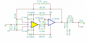
Worth prototyping:
Would like to see if the negative channel oscillations are present also with this?
Does not seem to simulate impossibly badly, anyway...?
This circuit should be very close to the circuit in the composite amplifier article. There it worked well. My concern is that LM1875 will be very difficult to arrange in parallel when you have little control of the gain and the gain of the LM1875 is so high that the OP-AMP will work in a signal range with less good THD. Else, you have to use an OP-AMP per LM1875 (that leaves control of the gain) and then parallel such blocks as they also do in the article.
i have two utc tda2030a here, their quiescent current is around 14mA with
+-13V supply...........
and two stm tda2050 with 57mA Iq at +-22V......(fdenys utc tda2050 was
27mA Iq)........
so the newer utc-tda seem to draw less Iq than the former stm-tda's.......less
power consumption
+-13V supply...........
and two stm tda2050 with 57mA Iq at +-22V......(fdenys utc tda2050 was
27mA Iq)........
so the newer utc-tda seem to draw less Iq than the former stm-tda's.......less
power consumption
- Home
- Amplifiers
- Chip Amps
- LM1875 in parallel configuration and used in a composite amplifier.