...building the parallel amp failed
Hi
i build 3 days ago the amp but i got strange outputs. the reason is not evaluated by me and actually i have no idea.
what happened:
i installed successfully the psu and it worked.
from previous test both amps (2 boards in parallel) l+R are working good at 4,459R load.
i installed everything checked some point about shortcuts...etc...and switched on and want to measure the DC offset but i got out of range at the mV setup at my DMM !!!😱 + i see my cap bank led´s soft blinking/bumping. i switched every thing off.😕 the voltage during this at the rails are jumping from 22-26V up/down. i found no high temperature at the chips. i installed the scope to look at the output.
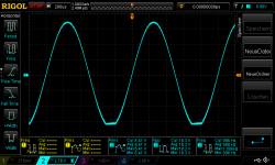
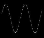
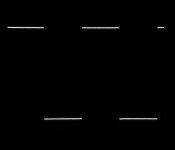
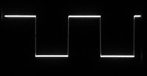
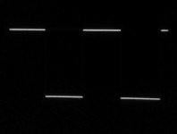
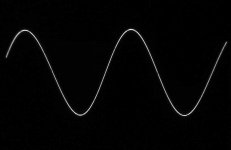
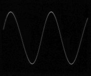
pic 1 Lchannel with 300mVrms input with 1khz - negative rail is cutted?
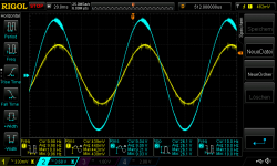
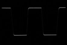
pic 2 Lchannel with 500mVrms input with 1khz - negative rail is cutted?
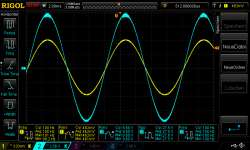
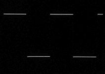
pic 3 Rchannel with 300mVrms input with 1khz - what´s that? -looks like curent protection
it was a very disappointing moment and I have no energy to look at the amp...
.....but today i looked and de-assembling everything and looked at R channel first. i disconnect the parallel cable to check ampR1 and ampR2 separate. ampR2 is dead. no input signal will be amplified
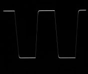
ampR1 looks good up to 440mV then it start to oscillating (too early because if you remember its starts about 570-590mVrms input)
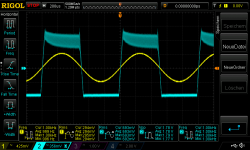
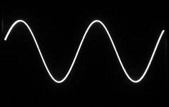
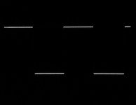
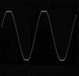
pic 4 ampR1 1khz 440mV input at 4,459R - starts to oscillating
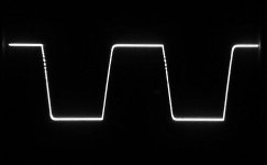
with lower frequency it gets worse!!!
pic 5 ampR1 100hz 450mV input at 4,459R - starts to oscillating
pic 6 ampR1 10hz 450mV input at 4,459R - starts to oscillating
so i guesstimate that this amp is "cracked" - ampR2 give no reaction.
what makes me so angry/confused is that i mount everything step by step - but some important failure i did -but i see nothing. - i just add the speaker cable and the input cables (post 350 was the step before)
https://www.diyaudio.com/forums/chi...ation-composite-amplifier-35.html#post6070217
i checked the metal pcb holders about shortening something but without success.
chris
Hi
i build 3 days ago the amp but i got strange outputs. the reason is not evaluated by me and actually i have no idea.
what happened:
i installed successfully the psu and it worked.
from previous test both amps (2 boards in parallel) l+R are working good at 4,459R load.
i installed everything checked some point about shortcuts...etc...and switched on and want to measure the DC offset but i got out of range at the mV setup at my DMM !!!😱 + i see my cap bank led´s soft blinking/bumping. i switched every thing off.😕 the voltage during this at the rails are jumping from 22-26V up/down. i found no high temperature at the chips. i installed the scope to look at the output.
pic 1 Lchannel with 300mVrms input with 1khz - negative rail is cutted?
pic 2 Lchannel with 500mVrms input with 1khz - negative rail is cutted?
pic 3 Rchannel with 300mVrms input with 1khz - what´s that? -looks like curent protection
it was a very disappointing moment and I have no energy to look at the amp...
.....but today i looked and de-assembling everything and looked at R channel first. i disconnect the parallel cable to check ampR1 and ampR2 separate. ampR2 is dead. no input signal will be amplified
ampR1 looks good up to 440mV then it start to oscillating (too early because if you remember its starts about 570-590mVrms input)
pic 4 ampR1 1khz 440mV input at 4,459R - starts to oscillating
with lower frequency it gets worse!!!
pic 5 ampR1 100hz 450mV input at 4,459R - starts to oscillating
pic 6 ampR1 10hz 450mV input at 4,459R - starts to oscillating
so i guesstimate that this amp is "cracked" - ampR2 give no reaction.
what makes me so angry/confused is that i mount everything step by step - but some important failure i did -but i see nothing. - i just add the speaker cable and the input cables (post 350 was the step before)
https://www.diyaudio.com/forums/chi...ation-composite-amplifier-35.html#post6070217
i checked the metal pcb holders about shortening something but without success.
chris
Attachments


Chris, I will look at your results in a moment.
I got my triple LM1875 ready end of the afternoon.
I tested each of the three channels individually and without load just to make sure they all worked before being connected by load balancing resistors (0.33 Ohm). They worked! Without load the clipped tops seemed oscillation free.
Then, a prudent engineer would have adjusted output offset and gain-match before connecting the three channels together.
BUT, I was curious to see if the LM1875 would "fight" when connected together. So without any adjustments, I connected first two and then three together. +/-18V supply, 1KHz and 10 Ohm loading. Input signal all the way until clipping.
The output from each LM1875 and the summed output looked just as in my test of single LM1875. Even a bit less "woolly" at the clipped tops than for single LM1875, probably due to a better layout. Fully controlled sine-wave until clipping. No mutual oscillation at clipping.
I tried square-wave until clipping and also that looked like individual LM1875.
I measured across the load balancing resistors with a cheap DMM put in the 2V AC range. Indication of fair load sharing considering no adjustment had been carried out.
So, a very first test is absolutely positive.
Tomorrow I will check output off-set (I will not do adjustment if in the order of 2mV) and gain-match which will be trimmed. The gain-match will be done statically (on DC) with a DMM due to much better precision.
Then, I will use my +/-24V power supply and try 8/4/2.7 Ohm loading.
I will post photos.
Last edited:
Chris, sorry to hear about your trouble.
Making two amplifiers with a gain of 22 work in parallel when you have a frequency dependent transfer function (the capacitor connected to the inverting input) is much more difficult. If you want to do parallel LM1875 as well and have two LM1875 boards in spare, prepare two boards in linear DC-coupling with a gain of -3.5, if possible. It will be much easier to handle and prevent from breaking down.
Your PIC 3 looks like my first amplifier where one side would collapse in HF oscillation and the chip get very hot very fast.
Fred's experiments with UPC-TDA2050 have convinced me that this is a better chip for our use. The same sound, same pin-layout, much cheaper in purchase, better current margin, temperature + current-overload protection and "genuine" (predictable behavior).
Count how many genuine LM1875 ICs you have left. Make sure you have at least one set of "best performance" LM1875 mono boards to be used in the future as a reminder of all your LM1875 work. Leave one LM1875 IC as spare for the future. Then, count how many LM1875 you have left for parallel experiments.
As you may already have got the feeling of, years of DIY amplifier experiments will leave you with far more amplifiers than you can use daily. Therefore, imagine a way where you can replace one amplifier construction with another amplifier construction in the same chassis such that chassis and power supply is reused for more amplifier boards during time.
The chassis and power supply are the expensive parts and should be reused. Obsolete (at least for a while) amplifier boards can be hidden away in a box in the basement such that your wife no longer notice them. A number of unused amplifier chassis stored away will leave your wife with the impression that this is an expensive hobby ("why do you need another?"). Boards in a box will catch no attention.
Last edited:
Chris, I will look at your results in a moment.
I got my triple LM1875 ready end of the afternoon.
I tested each of the three channels individually and without load just to make sure they all worked before being connected by load balancing resistors (0.33 Ohm). They worked! Without load the clipped tops seemed oscillation free.
Then, a prudent engineer would have adjusted output offset and gain-match before connecting the three channels together.
BUT, I was curious to see if the LM1875 would "fight" when connected together. So without any adjustments, I connected first two and then three together. +/-18V supply, 1KHz and 10 Ohm loading. Input signal all the way until clipping.
The output from each LM1875 and the summed output looked just as in my test of single LM1875. Even a bit less "woolly" at the clipped tops than for single LM1875, probably due to a better layout. Fully controlled sine-wave until clipping. No mutual oscillation at clipping.
I tried square-wave until clipping and also that looked like individual LM1875.
I measured across the load balancing resistors with a cheap DMM put in the 2V AC range. Indication of fair load sharing considering no adjustment had been carried out.
So, a very first test is absolutely positive.
Tomorrow I will check output off-set (I will not do adjustment if in the order of 2mV) and gain-match which will be trimmed. The gain-match will be done statically (on DC) with a DMM due to much better precision.
Then, I will use my +/-24V power supply and try 8/4/2.7 Ohm loading.
I will post photos.
Cool FF, fine that your amp is working up to this step 🙂
Thanks FF for your kind words.
....Making two amplifiers with a gain of 22 work in parallel when you have a frequency dependent transfer function (the capacitor connected to the inverting input) is much more difficult. If you want to do parallel LM1875 as well and have two LM1875 boards in spare, prepare two boards in linear DC-coupling with a gain of -3.5, if possible. It will be much easier to handle and prevent from breaking down.
what I cannot get in my head is:
i did the test exactly with this "amp block" successfully pages before- left and right separately and it works.
i think about my psu board and fuse board- but they are working.
earth + GND are connected...hmmm...
i go ahead tomorrow...step by step...again and again...
1000 times fall down --> 1001 times stand up😉🙂
Tested my triple-LM1875 this morning for output off-set. Inputs shorted.
With my +/-18V supply, I had +2.7mV / -1.0mV / +5.4mV off-set at the three LM1875 outputs (before the load balancing resistors).
But, the output off-set is supply voltage and temperature dependent. So I had to use my +/-24V supply.
With the +/-24V supply, I had +5.2mV / -1.5mV / +5.2mV off-set at the three LM1875 outputs.
This is fully within the LM1875 specifications having LM1875 gains of 3.5 times. But, it is a bit more than I hoped and compensation should be done before real power tests. That requires I implement the +/-15V regulators on the board and do the adjustment.
Again I deviated from disciplined behavior and tried the triple with the now +/-24V supply and the 10 Ohm loading. The common output passed to clipping at 21.5V without any sign of oscillation. With the light 10 Ohm loading, I hardly noticed any fine oscillation at the flat clipped tops. The fine oscillation at the tops may come with increased loading.
I now also have to make a 4.0V reference for adjusting the gain of the three LM1875 to be fully equal (for best load sharing). I will make the reference with a TL431.
Please be patient with me for some days before I am ready to continue with the real power tests.
Last edited:

1000 times fall down --> 1001 times stand up😉🙂
I feel your pain and frustration.
A few weeks ago I put my LM4780 into parallel operation with 0R15 resistors on the outputs. The gain resistors are 0.1% tolerance and both channels had low DC offset and remained low when paralleled.
Tested with a 8 ohm woofer and the heatsink got hot and blew a fuse on a rail on the DC supply. I thought I heard some strange distortion but could be wrong. Returned it to 2 channels and testing with 1 channel was fine with the heatsink luke warm and no issues.
Put it away as have never liked this module.
Thanks rabbitz for your warm words🙂
i like the LM1875 amp...so i will not give up.......now😀
chris
i like the LM1875 amp...so i will not give up.......now😀
chris
Self oscillation is vicious in the sense that it can be triggered at any moment (if potentially unstable) by start-up transients, signal spikes or temperature changes that previously did not cause problems.
In earlier LM1875 experiments, I noticed very fast heating of LM1875 ICs when such oscillation started. It seems likely that with such oscillation, you can no longer rely on proper protection from features implemented in the IC because the circuit itself is paralyzed by passage of high current from the supply without the usual circuit control.
Thus in short, you need not look for a mistake you made to explain the unfortunate outcome.
Today I managed to have my triple LM1875 amplifier adjusted. Both for output off-set and gain match.
The output off-set was compensated with fixed metal film resistors. After an hour of work, three compensation resistors were found and mounted. After adjustment, the off-set of each LM1875 was 0.7mV, 1.1mV and 1.1mV.
For the gain adjustment (static), I prepared a voltage reference with an output voltage of 3.93V. Using this voltage reference at the input of all the LM1875 simultaneously, I had individual output voltages of -13.42V, -13.38V and -13.39V. A voltmeter was connected between the output of the LM1875 with the highest output voltage and the output of the two other LM1875 in turn. By putting a high impedance resistor in parallel with the input resistor of the two LM1875 with less output voltage, it was possible to increase the gain a little and achieve the same output voltage as for the LM1875 with the highest output voltage. At the end, I read 13.43V at the output of all three LM1875 when the voltage reference was used as a negative input voltage. Check with a voltmeter between two outputs directly showed voltage differences of 3-4mV.
The amplifier was ready for a first test.
Pictures 1-4 are with an unregulated +/-24V power supply and no loading of the (common) output:
Picture 1: 1Khz, 40Vpp, no loading.
Picture 2: 1KHz, 46Vpp and saturation, no loading.
Picture 3: 1KHz, 30Vpp, no loading.
Picture 4: 10Khz, 30Vpp, no loading.
Pictures 5-8 are with an unregulated +/-24V power supply and 8 Ohm loading of the (common) output:
Picture 5: 1Khz, 36Vpp, 8 Ohm loading.
Picture 6: 10KHz, 30Vpp, 8 Ohm loading.
Picture 7: 1KHz, 30Vpp, 8 Ohm loading.
Picture 8: 1Khz, 41Vpp and saturation, 8 Ohm loading.
Still only very little oscillation at the clipped (saturated) tops.
Tomorrow, test with 4 Ohm load and 2.7 Ohm load (three 8 Ohm power resistors in parallel).
Attachments
-
 Triple1875_10KHz_30Vpp_8Ohm.jpg.jpg185.7 KB · Views: 75
 -
 Triple1875_1KHz_30Vpp_8Ohm.jpg.jpg129.7 KB · Views: 70
 -
 Triple1875_1KHz_Clip41Vpp_8Ohm.jpg.jpg170.8 KB · Views: 67
 -
 Triple1875_1KHz_36Vpp_8Ohm.jpg.jpg136.9 KB · Views: 249
 -
 Triple1875_10KHz_30Vpp_NoLoad.jpg.jpg137.8 KB · Views: 242
 -
 Triple1875_1KHz_30Vpp_NoLoad.jpg.jpg131.4 KB · Views: 255
 -
 Triple1875_1KHz_Clip46Vpp_NoLoad.jpg.jpg125.5 KB · Views: 245
 -
 Triple1875_1KHz_40Vpp_NoLoad.jpg.jpg128.7 KB · Views: 243
Last edited:
Hi FF
i am still not in the mood to go ahead with the amp🙄.
i really do not want to bother you - i am still not working at the composite amp and i have a bad feeling that i do nothing to help...😱
you wrote in post 383:
If you want to do parallel LM1875 as well and have two LM1875 boards in spare, prepare two boards in linear DC-coupling with a gain of -3.5, if possible. It will be much easier to handle and prevent from breaking down.
so mean i should use the board and build an inverted amp with a gain of about 3,5. but no 100pF cap for feedback...right
chris
More Triple-LM1875 test results. 4 Ohm, 2.7 Ohm and 2 Ohm loading. Still using my +/- 24V unregulated power supply that sagged a lot in voltage for the 2.7Ohm and 2 Ohm tests.
Pictures 1-4:
Pict 1: 1KHz, 24Vpp, 4 Ohm load.
Pict 2: 1KHz, clipping at 35Vpp, 4 Ohm load.
Pict 3: 1KHz, 24Vpp, 4 Ohm load.
Pict 4: 10KHz, 24Vpp, 4 Ohm load.
Pictures 5-8:
Pict 5: 1KHz, 20Vpp, 2.7 Ohm load.
Pict 6: 1KHz, clipping at 32Vpp, 2.7 Ohm load.
Pict 7: 1KHz, 20Vpp, 2.7 Ohm load.
Pict 8: 10KHz, 20Vpp, 2.7 Ohm load.
(Rail voltages sagged to +/-19.7V at output clipping level)
Pictures 9-10:
Pict 9: 1KHz, clipping at 29Vpp, 2 Ohm load.
Pict 10: 1KHz, 24Vpp, 2 Ohm load.
(Rail voltages sagged to +/-18.5V at output clipping level)
Conclusion:
My unregulated power supply that starts at above +/-24V and ends at +/-18.5V is too weak for real power handling tests. I will use my more powerful regulated power supply later.
The triple LM1875 can handle down to 2 Ohm loads corresponding to a 4 Ohm load if used in BTL coupling. The output power capacity needs to be tested with a better power supply. Take into account that for my LM1875 chips the protection cannot be relied upon.
At no moment was the amplifier unstable. The "wool" at the clipped tops increased with loading but behaved very predictable.
Before taking the amplifier to the limits, I will implement the OP-AMP control (composite configuration) similar to the one palstanturhin uses and actually try to listen to the amplifier.
Square-wave tests indicate a surprising stability and tolerance to capacitive loading.
I may try the 10nF/100nF/1uF capacitive loading first.
Attachments
-
 TripleLM1875_1KHz_SQ24Vpp_2Ohm.jpg271.3 KB · Views: 80
 -
 TripleLM1875_1KHz_Clip29Vpp_2Ohm.jpg196 KB · Views: 76
 -
 TripleLM1875_10KHz_20Vpp_2.7Ohm.jpg238.6 KB · Views: 71
 -
 TripleLM1875_1KHz_SQ20Vpp_2.7Ohm.jpg121.8 KB · Views: 74
 -
 TripleLM1875_1KHz_Clip32Vpp_2.7Ohm.jpg272.5 KB · Views: 67
 -
 TripleLM1875_1KHz_20Vpp_2.7Ohm.jpg318.3 KB · Views: 71
 -
 TripleLM1875_10Khz_24Vpp_4Ohm.jpg163.1 KB · Views: 75
 -
 TripleLM1875_1KHz_SQ24Vpp_4Ohm.jpg232 KB · Views: 77
 -
 TripleLM1875_1KHz_Clip35Vpp_4Ohm.jpg585.8 KB · Views: 74
 -
 TripleLM1875_1KHz_24Vpp_4Ohm.jpg555.1 KB · Views: 75
Last edited:
This is great progress!
Three comments:
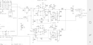
1 Linn used a small trimmer (VR601) to balance the gain of the two parallel TDA1514A in the Majik. After 20 years it is still reliable, I think concerns about small trimmers being unreliable are unfounded, and it would be easier to adjust this way and zero out parts variations. It would satisfy my urge to dial things in to a null. I think their strategy of using a very low value trimmer in series with an "almost there" resistor looks correct, because it will give the most useful range.
2. If you have a variac, you could crank up the voltage a bit and get more representative two ohm tests
3. Am curious what are the -3dB limits? The 10kHz square wave shows a touch more slope than I thought it would, while still looking excellent.
See attached Linn circuit for reference
Three comments:
1 Linn used a small trimmer (VR601) to balance the gain of the two parallel TDA1514A in the Majik. After 20 years it is still reliable, I think concerns about small trimmers being unreliable are unfounded, and it would be easier to adjust this way and zero out parts variations. It would satisfy my urge to dial things in to a null. I think their strategy of using a very low value trimmer in series with an "almost there" resistor looks correct, because it will give the most useful range.
2. If you have a variac, you could crank up the voltage a bit and get more representative two ohm tests
3. Am curious what are the -3dB limits? The 10kHz square wave shows a touch more slope than I thought it would, while still looking excellent.
See attached Linn circuit for reference
Attachments
Last edited:
Wow FF😱😎...thats looks very nice.
1
yes look first at the capacitive load with 8R-4R.
2
if that is fine then try 2.7R with better psu
3
2,7R or 2R and 100nF/1µF...etc
chris
1
yes look first at the capacitive load with 8R-4R.
2
if that is fine then try 2.7R with better psu
3
2,7R or 2R and 100nF/1µF...etc
chris
Hi Chris,
Let it rest for a while until the spirit is back.
You started the parallel amplifier with circuits that were not designed for that purpose. When you design parallel amplifier circuits, you have to aim at amplifier cells that behave as close as possible to one-another such that all outputs are (ideally) alike at any moment. The more gain and the more non-linearity in the transfer characteristic you have, the more likely it is that there are momentary deviations in the output voltages. Worst case, such output voltage differences can trigger oscillation.
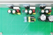
I knew that your starting point could be more difficult than ours (we have much less gain and a linear transfer function) but I have no experience with parallel amplifiers and perhaps your way would also work. Another issue is that if you want more amplifiers to work in parallel, they should be implemented with short signal lines (see my rather compact layout below). You did very well considering you had two boards. Exactly what killed one of your chips it is impossible to say.
At moments in a development sequence, it is important to stop up and evaluate if you are on the way into a dead-end and what is the right way ahead. If you start the parallel LM1875 construction now, you will be behind schedule-wise. If you try, you should rather make a low-gain version (inverting is most safe) and probably use two new LM1875 boards you can modify as needed such that you do not need to modify the existing mono amplifiers.
I will finish this triple LM1875 + BTL because we have passed the most difficult hurdles (I hope) and it has brought me a lot of necessary and sometimes surprising knowledge to be able to make an even better composite amplifier afterward.
Fred showed some very interesting results with the UPC-TDA2050. UPC-TDA2050 may be an even better choice than LM1875. When you use LM1875 in a composite amplifier, the particularly good sound of the LM1875 will to a large extent be dominated by the hopefully even better sound of the OP-AMP. TDA2050 has a sound very close to LM1875. Therefore, wether you use LM1875 or TDA2050 does not change the sound quality. But, 2x2 UPC-TDA2050 may do a job equal to 3x2 LM1875 due to better current capability. If you still like to take active part, I can suggest you to work on making a really well performing power stage with two UPC-TDA2050 working in parallel. The work will include confirming more of Fred's experiences like protection efficiency, and check how the TDA2050 behaves with gain below the recommended 10 times, sensitivity to capacitive loading, best Zobel compensation etc.
When palstanturhin made his composite test amplifier, it was not the OP-AMP circuit that caused much trouble - it quickly worked to very good THD. The “joker” for him was the surprising oscillation behavior of the power stage (the LM1875) and that took most of his time. If you could work on preparing a well functioning UPC-TDA2050 power stage with two ICs in parallel, then it will be ready for a next and better version of our project. I have just ordered some UPC-TDA2050 and I can send some of those to Vienna. It will be a pretty simple circuit that needs thorough testing.
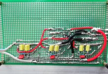
If you like to hear how six LM1875 working in parallel/BTL sound, I can find a homing pigeon when the board is finished and have it brought to Vienna for competent listening evaluation where you are much better than I. It is only mono. Else, the board will just end up in my box in the basement.
Let it rest for a while until the spirit is back.
You started the parallel amplifier with circuits that were not designed for that purpose. When you design parallel amplifier circuits, you have to aim at amplifier cells that behave as close as possible to one-another such that all outputs are (ideally) alike at any moment. The more gain and the more non-linearity in the transfer characteristic you have, the more likely it is that there are momentary deviations in the output voltages. Worst case, such output voltage differences can trigger oscillation.
I knew that your starting point could be more difficult than ours (we have much less gain and a linear transfer function) but I have no experience with parallel amplifiers and perhaps your way would also work. Another issue is that if you want more amplifiers to work in parallel, they should be implemented with short signal lines (see my rather compact layout below). You did very well considering you had two boards. Exactly what killed one of your chips it is impossible to say.
At moments in a development sequence, it is important to stop up and evaluate if you are on the way into a dead-end and what is the right way ahead. If you start the parallel LM1875 construction now, you will be behind schedule-wise. If you try, you should rather make a low-gain version (inverting is most safe) and probably use two new LM1875 boards you can modify as needed such that you do not need to modify the existing mono amplifiers.
I will finish this triple LM1875 + BTL because we have passed the most difficult hurdles (I hope) and it has brought me a lot of necessary and sometimes surprising knowledge to be able to make an even better composite amplifier afterward.
Fred showed some very interesting results with the UPC-TDA2050. UPC-TDA2050 may be an even better choice than LM1875. When you use LM1875 in a composite amplifier, the particularly good sound of the LM1875 will to a large extent be dominated by the hopefully even better sound of the OP-AMP. TDA2050 has a sound very close to LM1875. Therefore, wether you use LM1875 or TDA2050 does not change the sound quality. But, 2x2 UPC-TDA2050 may do a job equal to 3x2 LM1875 due to better current capability. If you still like to take active part, I can suggest you to work on making a really well performing power stage with two UPC-TDA2050 working in parallel. The work will include confirming more of Fred's experiences like protection efficiency, and check how the TDA2050 behaves with gain below the recommended 10 times, sensitivity to capacitive loading, best Zobel compensation etc.
When palstanturhin made his composite test amplifier, it was not the OP-AMP circuit that caused much trouble - it quickly worked to very good THD. The “joker” for him was the surprising oscillation behavior of the power stage (the LM1875) and that took most of his time. If you could work on preparing a well functioning UPC-TDA2050 power stage with two ICs in parallel, then it will be ready for a next and better version of our project. I have just ordered some UPC-TDA2050 and I can send some of those to Vienna. It will be a pretty simple circuit that needs thorough testing.
If you like to hear how six LM1875 working in parallel/BTL sound, I can find a homing pigeon when the board is finished and have it brought to Vienna for competent listening evaluation where you are much better than I. It is only mono. Else, the board will just end up in my box in the basement.
Attachments
- Home
- Amplifiers
- Chip Amps
- LM1875 in parallel configuration and used in a composite amplifier.