Looking pretty good, FF! Almost too good to be true... Try to add 1uF and see if that makes a difference for the square wave. You won't see much on the sine wave, except for some spurious oscillations (and of course heavy oscillations when the capacitance is much too high).
This is not good for my credibility:
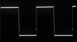
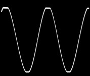
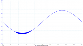
1uF film capacitor across the 10 Ohm load resistor, 1KHz, 5V per division on the oscilloscope. 2 photos with the 2.2uH//10 Ohm Thiele network, 1 without the Thiele network.
Photo 1: 1uF in parallel, Thiele network included, 20Vpp.
Photo 2: 1uF in parallel, Thiele network included, clipping at +/- 19.5Vp.
Photo 3: 1uF in parallel, NO Thiele network, 20Vpp.
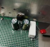
Photo 4: Test amp side 1.
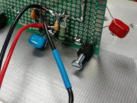
Photo 5: Test amp side 2.
Photo 3 was taken with the oscilloscope probe directly on the 1uF capacitor terminals.
Not easy to scare that IC!
Attachments

Last edited:
I am pretty much on line with cok666n that these are discarded items. Not put on the market by the brand holder TI but by wafer houses that are most likely not paid for the discarded items. Getting a little instead of nothing may be tempting.
I find it little likely that Asians themselves should make an own design which in most ways perform as well as the original LM1875 but they cannot manage to make a current limiter work. The LM1875 design is from something like 1990. In 30 years and with the flat grinding technique mentioned by Turbowatch2, the Asians can still not make a current limiter?
The flat grinding technique shows that without anything but a single chip, it is possible to make a copy. When I learned (a little) about semiconductor manufacturing, I was shown the huge master films, showing each semiconductor layer, that would be scaled dramatically down to arrive at real wafer dimensions. Without these master films or a copy of the films, no piracy production could take place.
Today the full wafer implementation is probably described in a single data-file. With a copy of that data-file you have all you need to produce exact copies. Further, in order to have "second source" producers of their ICs, the big brand manufacturers arranged that less important competitors could produce as second source. On top of that, imagine how many wafer houses in Asia that was used by brand manufacturers for the actual production.
I do not say that what became the result is legal or ethical, but the information needed to make copies was easily available. I see no reason for Asians to try with an own design and I find it unlikely that they are unable to include a functional current limiter. My guess is that many of the cheap items may have been discarded somewhere in test of genuine production lots.
We tend to assume an IC to be fake on basis of the price at which it was sold. Logically, we could call an LM1875 fake if not made by TI, disregarding the price. But, the LM1875 is in reality a circuit that performs within limits specified in the datasheet. My impression is that many price-wise "fake" chips will perform according to the TI datasheet at least on the parameters we test and find important. Is a cheap LM1875 that performs within the LM1875 datasheet an LM1875 or a fake if we do not know the real producer?
The genuine versus fake concern is complex. Evidently, if you want best certainty for performance, buy from a supplier you trust as supplying genuine items. If you buy cheap, you are less sure what you get but it does not mean that the item necessarily is useless or even that it has not been manufactured on order from the brand owner.
It is annoying when you are not sure what you actually get. For Europeans, the ambiguous to directly fraudulent marking of some food products is another example. It is far from only Asians who would engage in such activities. Art-fraud has taken place for centuries.
Design around fake chips is a waste of time because of the unpredictable results.
It can only be one shot diy endeovers with no future.
Whatever great result one can achieve, there is no guarantee one can reproduce it.
I understand your logic when you are aware of "best case" designs where your spend important time afterwards trying to make a poor design perform reasonably well.
High reliability design is based on taking all important parameter spreads for all components into account and arrive at (very conservative) designs that function in almost any case. I will claim that I can make an LM1875 design that will work with 90% of the LM1875 ICs that are on the market, genuine or fake. I do not say that the performance will be identical with any of these 90% ICs, but only that it will work correctly according to my specifications.
Of the 10% that will not work, I can discard far the majority with very simple tests.
First test!
8Vpp sqr-wave 20kHz. Thats it sofar...
Compensation capacitor 10pF at 5534, no other compensation.
Voltage gain 31x. Of which 1875 was at 2,2x.
As can be seen, ringing but no oscillation. Sinewave is of course clean.
Will do more tests tomorrow. THD, measured with the scope, was 0.001%, which is the bottom limit of it. Need to measure it with something else... My soundcard can do 0.0005%...
Lets see tomorrow...
One observation, 1Mega ohm is too high input impedance.
In my eyes, it looks like a really good start. The ringing is much above the audio range and dies out pretty fast. Already 0.001% is also a promising start. TI themselves indicate 0.002% for the NE5534.
Hi
According to the oscillating issue i tried to use the same paralleling board with different supply voltage. sorry i do not make a scope pic - so you have to trust me😀
me thinking is that the oscillating is "just" before the clipping event therefore i try to find a "relation" between supply voltage and the point when the oscillating is starting.
Here are my results: (supply with Rigol DP832)
+/- 18V supply - input 1kHz 440mVrms - output 9,22Vrms/27,1Vpp
supply - Vpp = "loss" --> 36 - 27,1 = 8,9V (24,72%)
+/- 20V supply - input 1kHz 490mVrms - output 10,2Vrms/29,9Vpp
supply - Vpp = "loss" --> 40 - 29,9 = 10,1V (25,25%)
+/- 25V supply - input 1kHz 590mVrms - output 12,3Vrms/36,1Vpp
supply - Vpp = "loss" --> 50 - 36,1 = 13,9V (27,8%)
+/- 28V supply - input 1kHz 6300mVrms - output 13,2Vrms/39Vpp
supply - Vpp = "loss" --> 56 - 39 = 17V (30,35%)
What do you think??. I remember on rabbitz recommendation to use the LM1875 just with 1%AC --> 21VDC..22VDC
chris
Hi Chris,
Your results are not much different from mine. My oscillation appears the moment I notice the top of the sine-wave starting being flat from clipping. Your oscillation seems to start a bit before mine. You use genuine LM1875, I probably fake. You have a gain of just above 22 in a non-inverting configuration, I have 3.5 in an inverting configuration.
The clearly better performance of genuine chips compared to fake is not obvious from these measurements. It seems consistent that the LM1875 will oscillate when close to saturation (clipping).
We have just finished a record-setting rain/snow period so I hope I can soon start implementing my "tripple".
Hope that your health is on top again.
What about the fake parts being relabeled 'different' parts? Let's say the asians have a huge stack of TDA2030 and sell them as LM1875. Not sure if the TDA has a current limiter on board, but otherwise they are pretty similar. This could also happen at wafer level; buy cheap dies and put them in a more expensive package...
How can you measure a 0.001% THD with a scope ?
16bits, + in its enhanced mode 20bits. FFT capable.
Picoscope 6 software.
For more accurate measurements I need more bits. I have 24 in my soundcard...
I try to measure something today with ARTA...
What about the fake parts being relabeled 'different' parts? Let's say the asians have a huge stack of TDA2030 and sell them as LM1875. Not sure if the TDA has a current limiter on board, but otherwise they are pretty similar. This could also happen at wafer level; buy cheap dies and put them in a more expensive package...
I agree with you that in case you have pin-compatible but other products you may have a very different performance. Your first LM1875 could have a different chip inside as the behavior is clearly inferior. The ones I got in 2 purchases behave very similar to LM1875. It could be TDA2050 but some I could take to +/-29V supply.
ICs like TA2020 and TA2022 have such unique features that there are no pin-compatibles and my guess is that those on the market today are based on original die information.
Hi FF and co-workers,
I did not want to criticize your use of "maybe LM1875" for this project. This is absolutely OK.
I would never have worked on a Ferrari if I had not started to experiment with a rotten Fiat 500 (around 1973) in my backyard . So any "useless" practice is better than learning nothing.
My point was to warn about to much refinement of your circuits. Especially Chris is trying to make things perfect that may not want to be 100% perfect.
If you try to remove some oscillation on a clipping sine wave, the measures that work with one chip will probably not net the same result on another example and can even be counterproductive.
The "real" chip maker´s refine any production over time. In the beginning the yield is often low, near the “end of live” almost any chip on a wafer will be 100% fine.
Intel often labeled CPU´s down, because the market needed "worse" (cheaper) ones, but production only gave A-quality. Today any single process is logged and stored, so tiny variations that give better results are easy to extract and can be introduced in future production run´s.
So after such a long production time, you can expect any real TI or National LM1875 as perfect as another. The fake China dirt is something else, here nothing is guaranteed, all spec´s are "maybe".
Something practical:
IMO the oscillations Chris sees may well be the limiters kicking in, it may be sooner or later with another chip. As these are, of course, not absolute (you could not use different voltage levels if they where), but relative to another voltage, with a less perfect made on-chip-resistor for example, these levels may be higher or lower. So my advice would be: Stick to the values that work well or the data sheet predicts.
I have spent countless hours in perfecting all kinds of circuits, usual you increase and lower part values and see what happens. Then you dial in the best compromise.
With such chip amps, it is in their genes they do not need precise values. The customers demand
maximum tolerance to all external part´s, so they have no rejects in production.
If the ultimate aim is sound quality, I may add some of my thoughts.
I would try to optimize the layout, place capacitors (mix of large electrolytic and smaller values, about 1:1000, film type) as near as possible to the main power legs. Then maybe solder a blank wire over power traces that lead in and out (cheap silver plated copper wire is perfect for this).
Such relative simple measures improve sound much more than many “serious” electronics guys want to admit.
I have as often as possible done such changes/ modification/ tuning (hate the word, but it fit´s) with a second unit that was left plain stock. Today I simply do not start such a work without a second example. This takes the fantasy out of the HIFI game and keeps Voodoo away. I´m a technician, not a poet.
Some mods that are considered huge improvements in tuner circles, did nothing, others were surprisingly effective. Usual common sense, generator and an oscilloscope show you what to do.
Just an example where science gets blurred: In some cases, the wires inside an power-, pre-amp or player, even as they are short compared to the ones on the outside, changed surprisingly much in the sound. I define good “sound” basically as absence of unpleasant noises, which make music or voices harsh, unnatural or muddy. You must know your music, off course. Then the A-B comparison will in most cases show the rest, like sound stage etc.
By the way, I never experienced a logical modification make the sound worse, some are just neutral to it, which can be a bit disappointing. Maybe they kick in with the next mod? Hope dies last...
The most important thing, by the way, is the A-B test before modifying anything! More than once one unit was defective, so repair before tuning. The same rule is with cars...
Just a short update about the THD.
Measured with 1kHz 1W 8R.
Loopback THD of my system is 0.0018%.
The amplifier added to the loop, THD still 0.0018%!!!
This means THD is less than 0.0005%. Below the range of my system.
Will continue with the testing...
Some observations though:
We might want to put as little gain as possible to the 1875 stage. That reduces the ringing at square wave. Will increase THD a little, but I think we can afford that. 🙂
Also makes it a bit more stable with capacitive loads.
Just a short update about the THD.
Measured with 1kHz 1W 8R.
Loopback THD of my system is 0.0018%.
The amplifier added to the loop, THD still 0.0018%!!!
This means THD is less than 0.0005%. Below the range of my system.
Will continue with the testing...
Some observations though:
We might want to put as little gain as possible to the 1875 stage. That reduces the ringing at square wave. Will increase THD a little, but I think we can afford that. 🙂
Also makes it a bit more stable with capacitive loads.
A very promising result. A slight problem may be to get hands on THD test gear that can measure THD levels when LM4562 or OPA1612 are being used.
In my posting #184 I made a calculation of what would be the gain needed in the LM1875 if an LM4562 is used as controlling OP-AMP. I arrived at 3.5 times amplification for the LM1875. With an OPA1622, the LM1875 gain can be lowered a little.
If we lower the LM1875 gain too much, the controlling OP-AMP runs into operation with high THD at high signal levels. Do you see 3.5 times as too high?
Last edited:
Hi FF and co-workers,
I did not want to criticize your use of "maybe LM1875" for this project. This is absolutely OK.
I would never have worked on a Ferrari if I had not started to experiment with a rotten Fiat 500 (around 1973) in my backyard . So any "useless" practice is better than learning nothing.
.............................................................................
Turbowatch2, once more I am convinced that you have more experience than I.
The comparison with your evaluation from Fiat 500 repair to Ferrari I find very useful for electronics as well. If you do not know how to make a Fiat 500 run, do not try with a Ferrari. But, making a Fiat 500 run is not at all trivial because it is the basic thing with no electronics to help you out. You need to understand all aspects of a combustion engine and car mechanics to succeed. My impression is that Fiat was and partly still is reputed for an electrical system even Fiat themselves never really mastered.
Our LM1875 project I will compare with a VW Golf – reliable performance at a moderate price. We will probably learn as much about the different design issues as if we had chosen a more powerful chip, but at much less cost.
Chris’ work with the mono LM1875 board I see as very important. Both does it show to less experienced DIYers that thorough work can be rewarded with surprisingly good performance, it mentions many of the design parameters to evaluate and it leaves a very efficient opportunity to get some “hands-on” experience. Many of us engineers or technicians tend to leave lab-work for administrative or managerial tasks to better earn a living and then we loose our feeling with electronic behavior. The LM1875 mono-board can be a crash-course in getting “hands-on” experience as you have many parameters you can experiment with. Chris did the experiments and revealed some improvements we all gain from. More importantly, I hope Chris felt that he gained on that electronic feeling we all need.
We will evidently keep your clever advise on layout and conductor issues in mind when we arrive at discussing layout at a later stage. You are right that it is already integral in Chris’ effort to fine-tune the mono-board performance and when we try to control fine HF-oscillation.
If we lower the LM1875 gain too much, the controlling OP-AMP runs into operation with high THD at high signal levels. Do you see 3.5 times as too high?
I have not done any tests yet at, or close to, the clipping levels. I try to measure something later today, to see how the 5534 performs there.
As can be noted from the tests so far, the datasheets are not quite comparable with this kind of configuration.
Lets see...
I like 5534 because it has the slew rate adjustable with a compensation capacitor. It also has the offset adjustment, which could be usefull for us.
And it costs nothing.
And the cherry on the cake, it seems the simulation model of it is quite accurate after all. We can simulate the circuit a lot and get usefull information from the simulations - which is nice.
I see these quite funny oscillations and wander how they influence sound.
When we build amps a very long time ago, we ran into the problem we could not measure distortion at home, because such stuff was only available at the university or an industry lab.
Also, our trust in measurements was a bit compromised, as amps, like Technics "New Class A" and other hyped stuff did not show an distortion in measurements, but still sounded horrible. On the other side, many amps, which where distorting much more, sounded fantastic. Even at that time, there where many people, often technicians with much more practical experience than us, that told us "good amps don´t sound anyhow" or "any amp with less than 0.1% TIM sounds identical." Just like today, ear less, better knowing idiots never die out.
Sometimes we could not run "flat out" tests, because it was too loud, later, when we used PA speaker, it got even worse.
So we ran the amps into a dummy load, but connected a good loudspeaker in parallel with a high load wire pot. Now we could listen to the sound the amp produced while being tortured, without stressing our ears and the neighbors.
This is not a very complcated or expensive procedure and could be modified for an earphone. So it may tell you when the oscillations become audible. Maybe they don´t bother the sound at all?
This is what I think is possible.
I have rulled out some of the possible causes:
Not a power supply, or decoupling issue.
Not a signal generator issue.
Removing the dummy load (8R, resistive), solves the oscillation problem completely????
So it must be some kind of a current issue?
Then about the gain at the 1875:
Reduced the gain from 2.2x to 1.5x.
Majour improvement to the squarewave response! Some overshoot but almost no ringing!
Also shifted the oscillation issue from -11V peak to -14V.
I will try with an other 1875, to rule that out...
Reducing gain under 20x is an experiment, but no solution. You can not reduce it to some kind of current amplifier and let the separate OP-amp do the voltage. The OP-amp for gain is a part of the chip´s structure.
I will, maybe, do the same test with a 3886, when I get my new signal generator, as I don´t want to repair my old one. Could be some special habit of the 1875 you are using in the test´s.
I will, maybe, do the same test with a 3886, when I get my new signal generator, as I don´t want to repair my old one. Could be some special habit of the 1875 you are using in the test´s.
Just to clear, we are on negative gain here. The 1875 operates in its inverted mode.
No problems with the positive rail on my proto.
Have it up and runing with a new 1875 in just a minute...
No problems with the positive rail on my proto.
Have it up and runing with a new 1875 in just a minute...
- Home
- Amplifiers
- Chip Amps
- LM1875 in parallel configuration and used in a composite amplifier.