No, just at the power terminals.
Try measuring at the IC pins and see. Likely enough you're dropping a little voltage through the traces on the board.
From the spec sheet I also notice that for 8ohm loads, THD is lowest just before clipping. Does this indicate that best perfromnace is when the amp is operating just before clipping at about 20 watts?
Perhaps that most of the THD+N is noise and that is lowest (comparatively) just before clipping
Try measuring at the IC pins and see. Likely enough you're dropping a little voltage through the traces on the board.
Might leave that for fear of shorting something 😥
No, just at the power terminals.
I wonder if the power resisters change value significantly when hot!
From the spec sheet I also notice that for 8ohm loads, THD is lowest just before clipping. Does this indicate that best perfromnace is when the amp is operating just before clipping at about 20 watts?
power resistor
please avoid this clip to connect these 2 resistor - solder this - its safer and better contact !
chris
Try measuring at the IC pins and see. Likely enough you're dropping a little voltage through the traces on the board.
Might leave that for fear of shorting something 😥
yes this is very delicate ! - try to find a point as near as possible.
but in my opinion for me more then 20W is ok.
the voltage drop is because of pcb traces , any connection/solder point, speakers terminal + internal resistance of the caps (ESR/ESL) etc..
chris
Perhaps that most of the THD+N is noise and that is lowest (comparatively) just before clipping
I guess that you have to be carefully if you drive with a speaker (complex load) and not a resistive load. so the bad thd come earlier !
at neurocrome ´s page i remember the complex work to achieve the complex load.
chris
"just before clipping" is when your signal to noise ratio is greatest.
So your THD+N(oise) will also be lower at this point.
From then on the onset of clipping will add to the THD part...
So your THD+N(oise) will also be lower at this point.
From then on the onset of clipping will add to the THD part...
power resistor
please avoid this clip to connect these 2 resistor - solder this - its safer and better contact !
chris
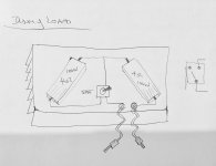
Is this 4/8 ohm dummy load suitable for these chip amps?
Attachments
Last edited:
hi
i personally would avoid a switch because you will be foreced to switch during power!
i use something like that...usd in cars setup... its soo cheap
search for 8 ohm resostors and build a board with 8R and 4R (8R parallel 8R)
for 2 channels ...big heatsink and fan is required...
https://www.amazon.de/MinticeTM-Lastwiderstand-Widerstand-Blinker-Schwanz/dp/B01FSFGVFY/ref=sr_1_3?__mk_de_DE=%C3%85M%C3%85%C5%BD%C3%95%C3%91&keywords=50W+kfz+widerst%C3%A4nde&qid=1567512601&s=gateway&sr=8-3
If it's anything like the kits I received, the chip is likely to be a TDA2050 or one of the others, hence the lower output. All 4 chips I have from these kits are not LM1875T.
If it's anything like the kits I received, the chip is likely to be a TDA2050 or one of the others, hence the lower output. All 4 chips I have from these kits are not LM1875T.
How can you tell?
Don't believe you can .. 2050 is NLA. For some time now
Even less likely to be genuine.
Do yourself a BIG favour simply buy a genuine lm 1875 chip form a 'Reputable' distributor .. these are ~4$.
Hardly a prohibitive price to eliminate All doubts.
Even less likely to be genuine.
Do yourself a BIG favour simply buy a genuine lm 1875 chip form a 'Reputable' distributor .. these are ~4$.
Hardly a prohibitive price to eliminate All doubts.
Last edited:
The difference between 25W and 22.5W @ 8 ohms is around half a volt. Based on the measurements taken I would argue the amp is performing within specification. Why stress about it.Don't believe you can .. 2050 is NLA. For some time now
Even less likely to be genuine.
Do yourself a BIG favour simply buy a genuine lm 1875 chip form a 'Reputable' distributor .. these are ~4$.
Hardly a prohibitive price to eliminate All doubts.
I understand that Indians and Chinese have frugality down to an Art form.
But now Aussies too ?
IMO yer peeing into the wind... for an 8$ advantage.. really? 🙄
But now Aussies too ?
IMO yer peeing into the wind... for an 8$ advantage.. really? 🙄
I retested my LM1875 kit I purchased a couple years ago. I used the parts supplied with the kit. I used my regulated supply set for +/- 25v. I scoped at the the leads of a 7.5 ohm load resistor. Output was 15.3 volts rms just before clipping or 31.2 watts. I verified the voltage with my multimeter.
Last edited:
I retested my LM1875 kit I purchased a couple years ago. I used the parts supplied with the kit. I used my regulated supply set for +/- 25v. I scoped at the the leads of a 7.5 ohm load resistor. Output was 15.3 volts rms just before clipping or 31.2 watts. I verified the voltage with my multimeter.
John , is that performance consistent with the spec sheet ?
Hi
if i remember right at the johnaudio tech video - the technical spec. are different but 20-30w is for both no problem - for me enough - but according to the datsheet the 1875 has better THD diagram
chris
if i remember right at the johnaudio tech video - the technical spec. are different but 20-30w is for both no problem - for me enough - but according to the datsheet the 1875 has better THD diagram
chris
I just ordered a pair of chips from Jaycar in Australia so we will see what they look like. The spec sheet on the website is from National Semiconductor.
Last edited:
Mine look exactly like TI LM1875 and not the others in the pictures in the link.
John , is that performance consistent with the spec sheet ?
The plot on the data sheet shows 25w at +/- 25v which may be a worst case measurement. 15.3v rms is 21.6v peak and this is what I would expect from the amplifier with 25v rails driving an 8 ohm load. If you measured, say 20w, this would mean 7v from rail to peak which is excessive.
I haven't read every post in this thread, but check voltages and scope at the screw terminals on the amp board to be sure you are not incurring losses somewhere along the way. You may lose a couple watts due to supply ripple and output signal through the protection board and wires. At 2 amps signal current, I wouldn't expect more than a few hundred millivolts drop unless there is excessive impedance somewhere.
- Home
- Amplifiers
- Chip Amps
- LM1875 Amp layout