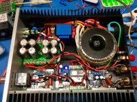
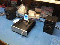
Assembly complete
(Skipping the clipping indicator for now)
Working OK but a few issues.
For 80% of the dial, the volume pot has little effect on the volume, it all happens in the last few mm. Would I be better of with a 10k audio pot than the 20K that is installed?
I have hum on the left speaker at low volume. The left channel is on the left amp in the photo. How do I troubleshoot that?
The mosfet shown on the speaker protection board gets to about +80c. Is that too hot and should I install a heatsink? One is indicated on the PCB but was not supplied.
Thanks
(New found respect for electronics technicians, what a fiddly job)
Attachments
Last edited:
Assembly complete
(Skipping the clipping indicator for now)
Working OK but a few issues.
For 80% of the dial, the volume pot has little effect on the volume, it all happens in the last few mm. Would I be better of with a 10k audio pot than the 20K that is installed?
I have hum on the left speaker at low volume. The left channel is on the left amp in the photo. How do I troubleshoot that?
The mosfet shown on the speaker protection board gets to about +80c. Is that too hot and should I install a heatsink? One is indicated on the PCB but was not supplied.
Thanks
(New found respect for electronics technicians, what a fiddly job)
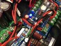
Not a MOSFET, it is a 12V linear regulator LM7812CV. 125C max operating temp. Think I will find a heatsink.
It was a late night last night, typing mistakes.
It is the amplifier closest to the toroid that is buzzing. And the buzz is gone when the pot is at zero volume but present at the same volume throughout the range ( I can hear it because the speakers don’t output until the end of the full turn). Wonder if the pot is dodgy as there is some LC/RC instability at max rotation.
I just read that the the mid rotation pint of the pot should match the amplifier impedence and some say this is about 25K (I don’t actually know) so do I need a higher value pot not lower?
Bulldog clip on the TO-220 dropped the temp by 20C for now.
Going to let it run all day.
Last edited:

Yes same layout.
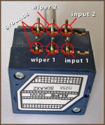
Volume pot
Volume pot
Attachments
Last edited:
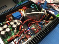
I’m not saying that this is what transformer shielding is supposed to look like 😀 but this made no difference.
Any advice on the volume pot selection? I have to fix that first.
Any advice on the volume pot selection? I have to fix that first.
Attachments
Last edited:
You have correctly identified the POT pins, however not how you connected it up.
Would be of help to have diagram of how you wired the pot into the circuit...
Would be of help to have diagram of how you wired the pot into the circuit...
You have correctly identified the POT pins, however not how you connected it up.
Would be of help to have diagram of how you wired the pot into the circuit...
The connections at the pot were fine. The polarity of the amp board input plug was wrong. I think they were assembled at the factory backwards.
No buzz anymore and normally functioning volume control - thanks Blu.
From my further reading I gather that these amps present a 22k impedence to the pot and that I should be using a pot with half or less resistance, ie 10K. What are the thoughts here and what would the consequences be?
Been running the amp now for several hours into some largish 8ohm 87dB 100W bookshelf speakers.
Big thanks to everyone on the Forum and John at JohnAudioTech (YouTube) for the inspiration and additional advice.
Last things to do is: add a heatsink to the voltage regulator on the relay board and secure all the wiring; get some feedback on volume pot choice - (anyone???); and maybe fiddle with a preamp and clipping indicator.
My intention is to mostly have it connected to an Apple Airport Express via a FiiO DAC (just for fun). My DIY Helium Micro Monitors may be the speakers I will keep connected On my work bench
The amp boards performance has been discussed in several places on the web and I probably won’t do much more testing, however here are some observations:
> @ 3/4 volume on iPhone through AEx and amp volume at 1/2 gives me nice listening volume in a large room with the larger bookshelf speakers
> supply voltage stable across volume range (playing music) at 27.5Vdc
> DC on the amp output is 3mVdc
> the chips don’t get any hotter that 35C with room at 20 and case top off
> zero audible hum between music tracks
> sounds good to my ears
The build was great fun and totally satisfying. Would have been nice to have made a custom chassis as it looks a bit like something you could buy off eBay, probably cheaper.
Cheers
Yes, much satisfaction. Just need someone with a musical ear to tell me whether it was worth it 😉
Here you go, one DIY stereo. Hope it inspires someone else.
(PS only consumes 15W at full vol)
Here you go, one DIY stereo. Hope it inspires someone else.
(PS only consumes 15W at full vol)
Attachments
Last edited:
OK glad to hear you sorted it out at last.
From what I remember a POT has a maximum output impedance of a quarter of it's total value - it varies depending on setting.
That and the fact that audio frequency signals do not normally need "impedance matching" (they don't reflect nor transmit detecteably), I'm not sure what improvement changing the POT would have.
If it sounds good I'd leave it....
Lovely neat case work too!
Last edited:
Great job! You must be very satisfied.
Forgot to say thanks for the initial layout guidance - that helped me get going.
🙂😀
I’m not saying that this is what transformer shielding is supposed to look like 😀 but this made no difference.
Any advice on the volume pot selection? I have to fix that first.
Suggest buying a 10K Dact 'Clone' stepped attenuator.
It sounds/better than that Alps Blu clone you have fitted.
Your ears will provide the proof.
Odd to see an entire amp built around 2$ Lm1875 Kits.
Great... if it sounds good .. just seems Ironic.
I'm surprised how it sounds. For 2$ there is nothing comparable although I suspect that my LM1875 are really TDA2030 but I don't care much either, as I said it sounds great.
I am using it only with headphones. The only modification I have made for this is to add a 47r/1W resistor in series to the output to avoid background noise with very sensitive headphones. I use a dual rail PSU (+/-17Vdc)
I would like to know if large heatsinks are really necessary if I use it for move speakers/monitors.
Those little boards are laid out nice with good grounding and bypassed right at the chip pins. They even included the RF low pass on the input. I decapped one of the ICs that came with the kit and the die is the same size as an authentic LM1875. Some sellers claim that the ICs are recovered. Perhaps from a production run of boards where the finished product was EOLed leaving orphaned boards.
OK But at 2$ each what is the reality/probability of being supplied with a Genuine Lm1875 Chip .. Really ?
Recycled assumptions aside
When Mouser charges ~3+ $ for one. Frankly it would IMO take a right Twit to go to all that amp building effort based on a hope and prayer.
When ~8$ would ensure genuine Lm chips.
Recycled assumptions aside
When Mouser charges ~3+ $ for one. Frankly it would IMO take a right Twit to go to all that amp building effort based on a hope and prayer.
When ~8$ would ensure genuine Lm chips.
Last edited:
OK But at 2$ each what is the reality/probability of being supplied with a Genuine Lm1875 Chip .. Really ?
Recycled assumptions aside
When Mouser charges ~3+ $ for one. Frankly it would IMO take a right Twit to go to all that amp building effort based on a hope and prayer.
When ~8$ would ensure genuine Lm chips.
All I can say is that the kit chip measured the same as the authentic ones. The fake TDA2040/2050 ICs I tested fall way short on power output when tested at the same supply voltage as the authentic TDAs. When I decapped the fake TDAs, they had much smaller die (about 1/2 the die area!) and the IC package looked different. The kit and authentic LM1875 look identical. Cost aside, I do believe they are authentic. OTOH, I don't trust the other components such as the resistors with the abnormally thin leads or the caps.
When I assembled my boards, I used all DigiKey/Mouser sourced parts just to be safe. I have a bin full of LM1875 ICs I bought when ST Micro EOLed most of their through hole TDA chips (TI axed some chips but thankfully kept the LM1875 in production). I keep the kit chips around for experimenting.
Last edited:
...OTOH, I don't trust the other components such as the resistors with the abnormally thin leads or the caps. ...
Yes, I also changed most of the other stuff (besides the X7R-Caps), but I think it's more or less more a mental than an audible upgrade.
Here in Germany I pay around 1,70€ which is roundabout 1,92$ for the little "China Blue"-Kit. I think at this Price one cannot expect more Bang for the Buck 😉.
The Amp works with the standard Components pretty well and that was, as I tried one of these for the 1st time, more than I expected.
The best one can do for the little Amp is to give it some 1000µF Electrolytics in the PSU, because this will give a real & immediately audible Improvement in Dynamics and Punch.
- Home
- Amplifiers
- Chip Amps
- LM1875 Amp layout