Why did you pick 2 Ohms for the parallel output inductor and resistor? I thought 10 Ohms was the more standard value to present a reasonable impedance out of band at high frequencies. I think I have seen 4.7 Ohms too.
Will do... Good advise. Lately it seems that when I do things, it works out like this...Why do it once when I can do it three times!
Why did you pick 2 Ohms for the parallel output inductor and resistor? I thought 10 Ohms was the more standard value to present a reasonable impedance out of band at high frequencies. I think I have seen 4.7 Ohms too.
So the Kenwood Basic M2 that I have uses 2.7/1w. I can change it. You think 10 ohms/1w would work better?
I hope so. Good luck! The following might help ensure success:
- Use a Dim Bulb Tester Powering Your Radio Safely with a Dim-bulb Tester
- Test each component before soldering. [I always do this with kits now.]
- After carefully checking the assembly put it aside and check it the next day carefully again before first power up.
- Build and test the stock design first before any mods. Give it a week or so of regular use and listening before mods.
- First power up with a current limited lab supply if you have it. LM317/LM337 dual supply is better than nothing and can prevent some
experiences. You can check bias control, output offset and listen at surprising volumes with a simple current limited lab or LM317/LM337 dual supply. Current and power is much more limited (and quickly limited) with such a supply.
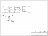
- Build and test your power supply alone first before connecting it to your new amplifier.
Before you power up the modified design you could even post clear pictures and others can try to spot issues before you power it up.
You know if I was thinkin.... I should just get the L12-2 Dual-Channel kit...$40 shipped! Then I could have just used my 400va 30-0-30 toroid!
Like I said...Why do it once when I can do it three times! UGH!!!😀
So the Kenwood Basic M2 that I have uses 2.7/1w. I can change it. You think 10 ohms/1w would work better?
I use 10 Ohms myself. I would not present a 2.7 Ohm load to an MX50SE at any frequency.
You know if I was thinkin.... I should just get the L12-2 Dual-Channel kit...$40 shipped! Then I could have just used my 400va 30-0-30 toroid!
Like I said...Why do it once when I can do it three times! UGH!!!😀
I was wondering that myself. But then again I bought several different LJM kits before I decided which one is most suitable for me. Each time I built one I learnt more and discovered two or three different designs that I did not know about earlier.
Right now my favorite is the LJM QUAD405-2 (with modifications).
You know if I was thinkin.... I should just get the L12-2 Dual-Channel kit...$40 shipped! Then I could have just used my 400va 30-0-30 toroid!
Like I said...Why do it once when I can do it three times! UGH!!!😀
Also keep in my that you might like the sound of the L20SE. I can't tell you if you would prefer the L20SE or one of the CFP designs like MX50SE, L12-2 or L20.5
You might even prefer a non-CFP design with a different VAS. Distortion In Power Amplifiers
I should stop leading you down the rabbit hole but you might even prefer something totally different like a KSA50 clone. This hobby is a bit addictive.
Last edited:
I just ordered the LJM L12-2 kit form...
It is well regarded. You should enjoy it.
If I want to go big, I just fire up my basic m2 with my Cerwin Vegas D8E's and I got a Who concert! But I **** the neighbor's off something terrible. Glad I hung on to it all these years. I bought it in 1986.
I guess I'll find out which of these sound good. Thanks for all the help.
I guess I'll find out which of these sound good. Thanks for all the help.
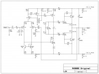
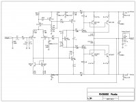
I was following this thread and schematic...😕
MX50SE LJM 2015
Is this wrong...😕
I know the diodes are facing the wrong way
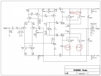
I posted the correct schematic for the MX50SE here (I reverse engineered it myself so I believe it to be correct)
MX50SE board mods
Yes Audio_tony. I used yours as a template then changed it to what mods should work. I am going to give it a shot...
Yes Audio_tony. I used yours as a template then changed it to what mods should work. I am going to give it a shot...
On the LJM 20.5 he uses 0.05 there. I used 0.12 (all I had) when I paralleled four CFP pairs.
So I would use 0.1 if you have it. If you don't then 0.2 will not cause a problem.
I wonder what the dependence (of distortion) is on emitter sharing resistor values on paralleled CFP outputs? Can anyone else comment and shed light on that?
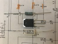
I was looking through my parts bins and found new old stock 0.1 ohm and I think 3 watt resistors that were used for soundstream amp emitter type out-puts.
Is 3 watt's going to be OK?
Attachments
Yes. There will now be two on each side (6W) at 0.05Ohms parallel resistance, compared with one 5W for the 0.2 or 0.22 Ohm resistor.
Yes. There will now be two on each side (6W) at 0.05Ohms parallel resistance, compared with one 5W for the 0.2 or 0.22 Ohm resistor.
These would be for the Emitter on each semi to +-vdc. I would leave the 0.2/5w on the Collector side alone...Correct?
Attachments
Last edited:
Yes. The added resistors are emitter sharing resistors so that the added paralleled output transistors share the current in a sufficiently equal fashion.
The other existing resistors are where you will measure the bias current which needs to be sufficiently stable as well as the correct value.
On first power up you need to check and set the bias current. Start from no bias and slowly work upwards as the amplifier heats up to normal operating temperature.
Also on first power up you need to check the output offset. The output offset and the bias control are a couple of important first diagnostics. If either are not working immediately power it off and find the fault. Use a Dim Bulb Tester or current limited laboratory supply for first testing. You don't very much more than your bias currents for the first checks to make sure nothing is in backwards, shorted or damaged.
If you let it draw current until a 5A slow blow fuse goes then you will likely have smoke before you find a serious fault. The components on the power amplifier board may (quite likely) blow up first and protect the fuse.
- Home
- Amplifiers
- Solid State
- LJM MX50 kit amp