Hello,You need a dual voltage supply, with positive and negative supply and ground. A single voltage charger will not work.
i ordered/received/wired this one
NEWSTYLE DC 12V 10A Commutation Adaptateur Transformateur d’alimentation Universal Regulated pour Strip LED Lights CCTV Ordinateur Projet Systeme de Securite: Amazon.fr: High-tech
it has 4 outputs : 2 * +12v 2* -12v and gnd
but same behaviour as with the PC charger...
what's wrong ? i think lack of groung reference...
R.
Are you sure of the dual outputs?
Is it not a single output supply?
It looks like one 12V supply (with two screw terminals connected to the same + connection of the single 12V supply and two screw terminals connected to the same - connection of the single 12V supply)?
Plus the one GND that is supposed to connect to your three wire AC plug. (The GND next to Line and Neutral?)
That looks like my single output 24V supplies and looks like it is made by the same factory.
Hello,
i ordered/received/wired this one
NEWSTYLE DC 12V 10A Commutation Adaptateur Transformateur d’alimentation Universal Regulated pour Strip LED Lights CCTV Ordinateur Projet Systeme de Securite: Amazon.fr: High-tech
it has 4 outputs : 2 * +12v 2* -12v and gnd
but same behaviour as with the PC charger...
what's wrong ? i think lack of groung reference...
R.
It might be helpful to study the following link:
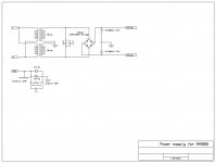
Power Supply for Power Amplifiers
It talks about the basics of a dual power supply for power amplifiers.
Perhaps someone else knows of a good starting reference with some pictures that they can share too?
Are you sure of the dual outputs?
Is it not a single output supply?
It looks like one 12V supply (with two screw terminals connected to the same + connection of the single 12V supply and two screw terminals connected to the same - connection of the single 12V supply)?
Plus the one GND that is supposed to connect to your three wire AC plug. (The GND next to Line and Neutral?)
That looks like my single output 24V supplies and looks like it is made by the same factory.
yes i think so too... i'll send it back
and yes again about the factory, all these PSU look exactly the same, only the name of the distributor changes 😎
tirol29; said:and yes again about the factory, all these PSU look exactly the same, only the name of the distributor changes
Yes. I noticed that too. I stay far away from the specifications because I don't expect any luck on warranty returns when the identical product is sold under 100 different weird company names.
It might be helpful to study the following link:
Power Supply for Power Amplifiers
It talks about the basics of a dual power supply for power amplifiers.
Perhaps someone else knows of a good starting reference with some pictures that they can share too?
it's ok 🙂
if i don't find something not too expensive i'll go with ordinary PSU transformer + diodes + caps . it's not intended for hifi high grade 😎
i have a transformer 2x12v CT but only 1A, not sure it will make it, even if most of the time the real listening power will be 1or2 W, as PC speaker system in a bedroom 🙄
it's ok 🙂
if i don't find something not too expensive i'll go with ordinary PSU transformer + diodes + caps . it's not intended for hifi high grade 😎
i have a transformer 2x12v CT but only 1A, not sure it will make it, even if most of the time the real listening power will be 1or2 W, as PC speaker system in a bedroom
Those LJM designs have low Icq (idle current) and if you are listening at 1 or 2W you might be surprised what you can get from that transformer in a small room. Put an appropriate fuse in and give it a try. Build the supply (not connected to the amplifier) and test it out with a meter first.
hello kozard,
built the psu and tested all.
Very nice sound with my diy baffles :
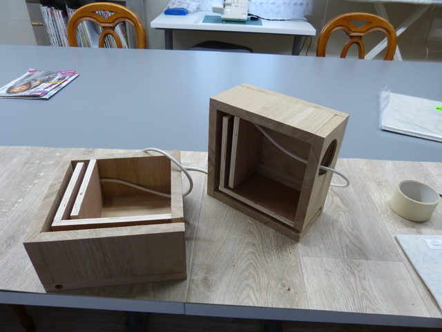
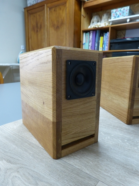
the speakers are wide band Dayton audio DMA80-4
i don't know at which real output power i am, and because i know even less how much amps consumed at primary, i've put a 0,4A fuse.
The transformer is warm after some times at quite loud power. Then , to be more secure while in enclosure, i ordered another one with double power : 48VA for 20€...
thanks for everything and have a good sunday.
Roland.
Last edited:
hello kozard,
built the psu and tested all.
Very nice sound with my diy baffles :
the speakers are wide band Dayton audio DMA80-4
i don't know at which real output power i am, and because i know even less how much amps consumed at primary, i've put a 0,4A fuse.
The transformer is warm after some times at quite loud power. Then , to be more secure while in enclosure, i ordered another one with double power : 48VA for 20€...
thanks for everything and have a good sunday.
Roland.
Very good! Enjoy!
Nice looking speakers too. Right now I have too many amp and DAC projects but I am tempted to try baffles.
DMA80’s on-axis response indicating a ±4.5dB SPL variation from 300 Hz to 13.5 kHz with sharp break up mode peaking modes at 23 kHz.
Note the distortion in the low frequency range. This speaker is suitable for 300Hz satellites in 2.1 system.
Test Bench: The Dayton Audio DMA80-4 3” Full-Range Driver | audioXpress

Note the distortion in the low frequency range. This speaker is suitable for 300Hz satellites in 2.1 system.
Test Bench: The Dayton Audio DMA80-4 3” Full-Range Driver | audioXpress
Last edited:
if you don't have it yet it's time to invest in a router or best in a table router.... I am tempted to try baffles.
I did my own table.
again one more thing :
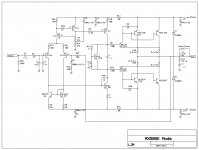
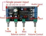
i use this preamp

if powered through PC charger really nice, does its job, but if wired to the PSU i made i get hum. Do you have an idea how to get rid of that ?
i invited the end user (my wife 🙂) for a listening and she liked a lot and ask me to push it..😛 then the new transformer will be welcome 🙄Very good! Enjoy!
again one more thing :
i use this preamp
An externally hosted image should be here but it was not working when we last tested it.
if powered through PC charger really nice, does its job, but if wired to the PSU i made i get hum. Do you have an idea how to get rid of that ?
Since you don't get hum when using a separate supply it sounds like it could be a grounding issue. Hum is at the powerline and harmonic frequencies for such a problem.
I know (sometime in the last year) someone answered a similar question (no idea which thread) and they drew some nice diagrams demonstrating how to do the grounding. I wish I could remember which thread and post so that I can reference.
Can anyone suggest a reference for clearly explaining how to ground a power amplifier and a preamp?
I use a separate power supply and never share the preamp or DAC supplies with the power amplifier supplies. I think that is what is done 99% of the time.
To avoid ground loops at 1st you can try to connect preamp and power amp ground only by one point (preferably at supply filtering capacitors 0v).
In doing this you can try to disconnect signal ground between preamp and amp, if signal ground is a shield, you can connect it to ground only at one side.
In doing this you can try to disconnect signal ground between preamp and amp, if signal ground is a shield, you can connect it to ground only at one side.
hello,
here the way it is wired
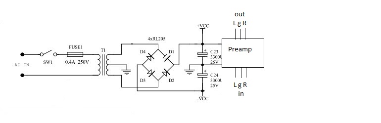
i tried disconnecting the signal ground at one side at the time. no way
this doc seems to provide a solution,
link and file attached :
https://www.ti.com/general/docs/lit/getliterature.tsp?baseLiteratureNumber=sloa143&fileType=pdf
and i've read here that somebody advise to cut the pcb between the gound and input ground and to re-connect them through a resistor of low value
value to be from 5R to 20R
Attachments
Last edited:
if i only connect the +16v to the preamp, and not the ground i get the sound plus the hum ?????
i've made the mod on one channel, 10R between input ground and general ground on the amp, no change....
thus the main problem is as the preamp were not grounded at all ? or something else ?
i've made the mod on one channel, 10R between input ground and general ground on the amp, no change....
thus the main problem is as the preamp were not grounded at all ? or something else ?
Last edited:
I would leave them at 68 ohm, the final transistors in this way would dissipate more power and the drivers lower. Be aware that D1 and D2 are both reversed: if they were connected that way, there would be a decent bang when you feed the amp.
Maybe that in your interpretation of the PCB maybe you are confusing R5 with R3 and R14 with R29 ?
No...R29 (47ohm) connects to the collector of Q13 and base of Q14 and then to the emitter of Q14.
R3 (47ohm) connects to the collector of Q11 and base of Q12 and then to the emitter of Q12.😕
Had me double check...
So your saying I should change these to 68 ohm?
MX50SE board mods
After reading all the threads on the MX50 and MX50SE (more than once) and gathering info for improvements, I decided to try and put it all together. Before I finalize the install of all this into a chassis I wanted to make sure I wasn't missing anything and possibly get more opinions, suggestions from experienced people on this forum.
1. Was told to try and use +-25vdc on the rails. K, got it.
2. Purchased a AS-4218 400VA 18V - 0 - 18V Toroid.
3. Purchased a KBPC3504 35amp Full wave bride.
4. Purchased two 10,000uf/35v audio grade caps from mouser
5. So with 25v rails I can use 35v capacitors on the board which allows
470uf/35v cans to fit on the board.
Plus, correct me if I'm wrong, Caps should be at about 80% of the voltage
to function correctly at the rated uf.
6. Replace the 470uf/16v cap with 1000uf/6.3v. Does it have to be NP?
7. Replace R13 (1k) with a 2k multi turn pot.
8. Created two 1.5uH air inductors for the out-puts and 2 ohm 2w resistors
paralleled with them.
9. Purchased a Gump's grocery Speaker Protection Board from Amazon.
10. Purchased four of 2sa1186 and four 2sc2343 from Digi-Key. All have case
code Y.
11. Purchased four 5watt 0.2 ohm for adding the extra pair of final transistors.
12. When adjusting bias for this configuration, I guess I could do the notch
distortion method but then of course check the voltage across the
collector resistors.
Am I missing anything?
I am not planning for an auditorium sound system just something that sounds excellent.
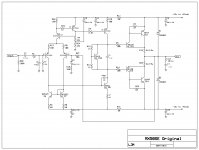
I've attached the stock and modified .SCH that can be edited using ExpressSCH. It's a free download program. I had to change these to a .txt file so you have to change the extension back to .sch after you download it
After reading all the threads on the MX50 and MX50SE (more than once) and gathering info for improvements, I decided to try and put it all together. Before I finalize the install of all this into a chassis I wanted to make sure I wasn't missing anything and possibly get more opinions, suggestions from experienced people on this forum.
1. Was told to try and use +-25vdc on the rails. K, got it.
2. Purchased a AS-4218 400VA 18V - 0 - 18V Toroid.
3. Purchased a KBPC3504 35amp Full wave bride.
4. Purchased two 10,000uf/35v audio grade caps from mouser
5. So with 25v rails I can use 35v capacitors on the board which allows
470uf/35v cans to fit on the board.
Plus, correct me if I'm wrong, Caps should be at about 80% of the voltage
to function correctly at the rated uf.
6. Replace the 470uf/16v cap with 1000uf/6.3v. Does it have to be NP?
7. Replace R13 (1k) with a 2k multi turn pot.
8. Created two 1.5uH air inductors for the out-puts and 2 ohm 2w resistors
paralleled with them.
9. Purchased a Gump's grocery Speaker Protection Board from Amazon.
10. Purchased four of 2sa1186 and four 2sc2343 from Digi-Key. All have case
code Y.
11. Purchased four 5watt 0.2 ohm for adding the extra pair of final transistors.
12. When adjusting bias for this configuration, I guess I could do the notch
distortion method but then of course check the voltage across the
collector resistors.
Am I missing anything?
I am not planning for an auditorium sound system just something that sounds excellent.
I've attached the stock and modified .SCH that can be edited using ExpressSCH. It's a free download program. I had to change these to a .txt file so you have to change the extension back to .sch after you download it
Attachments
After reading all the threads on the MX50 and MX50SE (more than once) and gathering info for improvements, I decided to try and put it all together. Before I finalize the install of all this into a chassis I wanted to make sure I wasn't missing anything and possibly get more opinions, suggestions from experienced people on this forum.
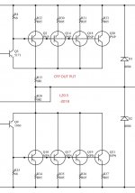
Please see the attached schematic to see how to add emitter resistors for current sharing in a paralleled CFP output. They must be in the emitter of each output.
Attachments
6. Replace the 470uf/16v cap with 1000uf/6.3v. Does it have to be NP?
No.
11. Purchased four 5watt 0.2 ohm for adding the extra pair of final transistors.
I have used 0.12 Ohm each for paralleling four CFP pairs and LJM uses 0.05 Ohm in the L20.5
If your outputs are well matched you can use those lower values.
12. When adjusting bias for this configuration, I guess I could do the notch
distortion method but then of course check the voltage across the
collector resistors.
I measure the distortion (at several power levels) while I adjust the bias and observe how a particular amplifier behaves.
You can also use this software (Room Eq Wizard) and method with the (power amplifier) adapter cable: Howto - Distortion Measurements with REW
REW is pretty amazing software. I also used it to measure my speaker impedance. They were rated as 8 Ohms "Compatible" and they measured 4 Ohms with a dip down to something like 3.5 Ohms.
Always monitor the voltage across the emitter resistors and of course check your offset voltage before starting too.
Last edited:
Am I missing anything?
Please see the following two links with regards to grounding and your loop breaker which I see (in your third schematic) has 5A diodes:
Earthing (Grounding) Your Hi-Fi - Tricks and Techniques
Audio Component Grounding and Interconnection
- Home
- Amplifiers
- Solid State
- LJM MX50 kit amp