hello,
i've just received all the material to build the 2 mx50se, and i have 2 questions:
1. while verfying all components it appears that i have an electrolytic capacitor of 10µF instead of a ceramic one. would that be a problem ?
thats's the only one of this value, i think C6 even if noted 105 on the schematic, on the pcb it's 106.
2. would it be better to put a silicon pas behind the drivrd 669 and 649 ?
thanks
hello,
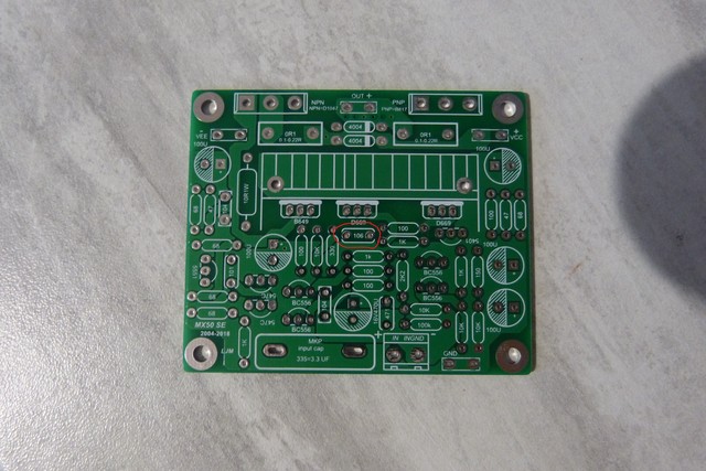
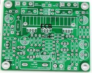
here the picture of the pcb, the condensator is the one circled in red
i've built the amps with the electrolytic, will see...
any thoughts ?
i've put some artic pc cooling paste behind the drivers.
before going on, another question regarding cooling:
these amp are due to go in a pc speaker system for my wife, then i'll run them under 12v and connect to wide band speaker of 4ohms 25w nom. 50w max.
i have this alu cooler
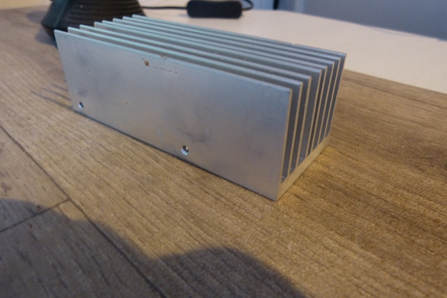
dimensions : L 110mm H 37mm D 45mm
is it enough to cope with the both amps ?
i've seen here another question that has been raised but not anwered (or i misses it) about the effect of changing the 330ohm resistor to 470 ohm , said to change the gain from 32dB to 22 dB .
Will it be interesting in my case where i don't need to shake the walls" ? 🙄
would appreciate a lot to get answers from more expert people than myself 😉
roland.
here the picture of the pcb, the condensator is the one circled in red

i've built the amps with the electrolytic, will see...
any thoughts ?
i've put some artic pc cooling paste behind the drivers.
before going on, another question regarding cooling:
these amp are due to go in a pc speaker system for my wife, then i'll run them under 12v and connect to wide band speaker of 4ohms 25w nom. 50w max.
i have this alu cooler

dimensions : L 110mm H 37mm D 45mm
is it enough to cope with the both amps ?
i've seen here another question that has been raised but not anwered (or i misses it) about the effect of changing the 330ohm resistor to 470 ohm , said to change the gain from 32dB to 22 dB .
Will it be interesting in my case where i don't need to shake the walls" ? 🙄
would appreciate a lot to get answers from more expert people than myself 😉
roland.

Some thermal greases can cause short circuits. Check resistance.
For the electrolytic capacitor to choose the correct polarity.
For the electrolytic capacitor to choose the correct polarity.
hello,
i've just received all the material to build the 2 mx50se, and i have 2 questions:
1. while verfying all components it appears that i have an electrolytic capacitor of 10µF instead of a ceramic one. would that be a problem ?
thats's the only one of this value, i think C6 even if noted 105 on the schematic, on the pcb it's 106.
Is it a yellow monolithic ceramic capacitor? Can you post a picture? I have built many LJM kits and that capacitor across the Vbe multiplier has never been an electrolytic. Always a monolithic ceramic capacitor as shown in my attached image. Please post a picture of your capacitor to prevent a mixup.
2. would it be better to put a silicon pas behind the drivrd 669 and 649 ?
thanks
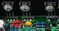
All the 669 and 649 that I have used are plastic encapsulated as shown in the attached picture. I use a little bit of silicone thermal paste behind them without any problems.
Attachments
i've seen here another question that has been raised but not anwered (or i misses it) about the effect of changing the 330ohm resistor to 470 ohm , said to change the gain from 32dB to 22 dB .
Will it be interesting in my case where i don't need to shake the walls" ? 🙄
It really depends on the output level from your source which could be a bare DAC or perhaps you have a pre-amplifier. So it depends on the gain of your pre-amplifier (if any) and the output level of your source (DAC, CD player, computer, etc.)
When I find the gain is too high (and my volume control is always near minimum) I reduce the gain. I have done this on several LJM kits without any issue. I have read that LJM tends not to use pre-amplifiers. I find his kits often have gain that is a bit higher than I prefer.
I don't like having excessive gain and then excessive attenuation in my system.
thanks kozard for reply 🙂Is it a yellow monolithic ceramic capacitor? Can you post a picture? I have built many LJM kits and that capacitor across the Vbe multiplier has never been an electrolytic. Always a monolithic ceramic capacitor as shown in my attached image. Please post a picture of your capacitor to prevent a mixup..
it's definitely an elecrolytic one, same make as the others : Nichicon
no need for a picture, but can i stay with it , if so which sens to put it, i mean where should the + and - go ?
the amp has not been fired yet so if really a bad idea i will have to request from vendor, or buy new ones, at expensive postage fees 😡
second, is the value of 10µf a need ? as i saw many picture of the pcb with 105 printed instead of 106 on mine ? i ask as if i can find 1µf from trashbin pcb, i will do that. Should be more common value in ceramic.
and if i may ask more from your time, do you have any idea about the heat sink ? i'm thinking of sawing it in the middle of the length 🙄
thanks again for all
Roland.
re,
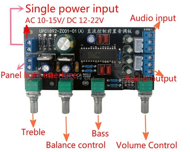
i'm going to use this preamp, if it is a preamp...
so i don't know the ratio in terms of output, the main input will be the headphone output from a PC (green jack)
i kept the resitor (330R) a bit lifted, so it will be more easy to remove .
i'm going to use this preamp, if it is a preamp...
so i don't know the ratio in terms of output, the main input will be the headphone output from a PC (green jack)

i kept the resitor (330R) a bit lifted, so it will be more easy to remove .
thanks kozard for reply 🙂
it's definitely an elecrolytic one, same make as the others : Nichicon
no need for a picture, but can i stay with it , if so which sens to put it, i mean where should the + and - go ?
the amp has not been fired yet so if really a bad idea i will have to request from vendor, or buy new ones, at expensive postage fees 😡
second, is the value of 10µf a need ? as i saw many picture of the pcb with 105 printed instead of 106 on mine ? i ask as if i can find 1µf from trashbin pcb, i will do that. Should be more common value in ceramic.
In that position I have seen 1uF all the way to a huge 100uF 50V (in a Denon AVR-3808). From my understanding a 10uF electrolytic will work fine. The capacitor leads are connected to the first two leads of the Vbe multiplier 2SD669 (traces on the back of the PCB). The 2SD669 pinout is ECB so you need the negative lead connected to the first pin (left side) and the positive lead connected to the second pin which is the right side of the capacitor footprint. See the illustration I have attached.
I suggest you still upload a photo of the capacitor, the PCB and the entire kit. Something seems wrong. I have quite a few LJM kits and I have never seen LJM use an electrolytic there before. I wonder if your kit is genuine or if something is perhaps off. Where did you buy the kit?
and if i may ask more from your time, do you have any idea about the heat sink ? i'm thinking of sawing it in the middle of the length 🙄
The heatsink is small but I think you are using lower supply voltages. What are the rectified positive and negative supply voltages you are using?
Are you familiar with using a DBT (Dim Bulb Tester) to safely power up the first time (to try to prevent disaster)?
Attachments
Last edited:
re,
i'm going to use this preamp, if it is a preamp...
so i don't know the ratio in terms of output, the main input will be the headphone output from a PC (green jack)
i kept the resitor (330R) a bit lifted, so it will be more easy to remove .
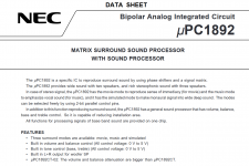
I am not familiar with that board. I don't know if that is a preamp or if it is a surround sound processor. (See attached datasheet screenshot.) I don't know what gain it has (if any).
For small computer speakers and close listening levels you might find that you have a bit too much gain. However I don't know what your input signal level will be.
Attachments
I suggest you still upload a photo of the capacitor, the PCB and the entire kit. Something seems wrong. I have quite a few LJM kits and I have never seen LJM use an electrolytic there before.
it's ok, i was not aware of bipolar electrolytic

i will use + and - 12V only.The heatsink is small but I think you are using lower supply voltages. What are the rectified positive and negative supply voltages you are using?
yes i know but i never built or used it even when i built a guitar tube ampAre you familiar with using a DBT (Dim Bulb Tester) to safely power up the first time (to try to prevent disaster)?
Valco/supro S6422TR
thanks again for all,
Roland
I did so, already had a toroidal 500VA 30+30Vca (42+42Vcc) transformer, but bought the two toroidal you see in the picture 160VA 19+19Vca (27+27Vcc potentially a bit more of 40W on 8Ohm by my amps in a pure dual mono).
This supplier on Amazon have them: Trasformatore Toroidale 160 VA 2 x 115 V: 2 x 18 V: Amazon.it: Commercio, Industria e Scienza
So I've done some price compare and another toroid will cost more than one of these, LJM L20 SE...It will fit nicely in the chassis/ heatsink I built. So I'm waiting for it to arrive.🙂 I will make a schematic for it and Ask you the best method for a multiturn pot to adjust bias on this thing...
it's ok, i was not aware of bipolar electrolytic
Odd that it is a 10uF BP. Not bad, just odd since I have not seen that in any LJM kit before.
i will use + and - 12V only.
That is pretty low so I don't think you will generate too much heat. The heatsink could be fine. I would not cut it in half (I usually mount both channels to the same heatsink). But of course make sure you mount the power transistors with mica or silpads.
So I've done some price compare and another toroid will cost more than one of these, LJM L20 SE...It will fit nicely in the chassis/ heatsink I built. So I'm waiting for it to arrive.🙂 I will make a schematic for it and Ask you the best method for a multiturn pot to adjust bias on this thing...
Schematics are already on this forum😱 😎
hello all,
i've finished and fired both amps. nothing blown up 😎
but, the sound is just awful, and far away from what i've read about this amp.
it's the same for both of them.
DC power is given by a PC charger . I've two of them one at 12V/5A and another 12..24V/6A = same problem with both.
input is either a mp3 player or a hedphone output from a PC (which is the final intended connexion).
I suspect a ground problem.
i've read somewhere (here i suppose) that the ground should be cut between INPUT-Gnd and SPKR-Gnd and then connect them through a resistor.
Lowest value i have is 22 Ohms.
Any thoughts or advice ?
You need a dual voltage supply, with positive and negative supply and ground. A single voltage charger will not work.
Hello,
I have purchased this kit in order to bring back to life and old amplifier. I would like to simulate it beforehand in order to check the behaviour with my power supply (+/- 25V).
I would like to use the output transistors included in the kit ( d1047 - B817).
Any one willing to share the spice models for this transistors?
Thanks
Hello,
I have purchased this kit in order to bring back to life and old amplifier. I would like to simulate it beforehand in order to check the behaviour with my power supply (+/- 25V).
I would like to use the output transistors included in the kit ( d1047 - B817).
Any one willing to share the spice models for this transistors?
Thanks
Post 32 talks about Spice, maybe get info from him...
- Home
- Amplifiers
- Solid State
- LJM MX50 kit amp