Grounding
I was following Elliott Sound project #04...???
Power Supply for Power Amplifiers
Is he wrong? 😕
I was following Elliott Sound project #04...???
Power Supply for Power Amplifiers
Is he wrong? 😕
Well I was following the same author at this link where he uses a 35A bridge:
Earthing (Grounding) Your Hi-Fi - Tricks and Techniques
When you followed the other ESP link did you include the 5A fuse when you used the 5A SB5100 diodes? I don't see a fuse in your third schematic. Personally I would use a heavy bridge for safety margin. (And include the fuse shown by ESP.)
Maybe an expert can comment/confirm/advise.
Last edited:
Please see the following two links with regards to grounding and your loop breaker which I see (in your third schematic) has 5A diodes:
Earthing (Grounding) Your Hi-Fi - Tricks and Techniques
Audio Component Grounding and Interconnection
So Elliot Sound is using a 35amp bridge instead of what he did in project #04.
I will do the same... Thanks for the information.

Well I was following the same author at this link where he uses a 35A bridge:
Earthing (Grounding) Your Hi-Fi - Tricks and Techniques
When you followed the other ESP link did you include the 5A fuse when you used the 5A SB5100 diodes? I don't see a fuse in your third schematic. Personally I would use a heavy bridge for safety margin. (And include the fuse shown by ESP.)
Maybe an expert can comment/confirm/advise.
Yes It will be fused. Also, I may add fused rails...
I fused my rails and my test speakers* when starting out with a brand new DIY amplifier. But I found that a very small fast fuse is needed to protect output transistors. And then while doing distortion measurements with REW I found that the small fuses heat and produce a little bit of distortion. (I was testing an ultra low distortion design.) I suppose some people will dispute that but you can actually measure it (on ultra low distortion designs).
*Why? My first speaker protection board from Ebay turned out to have a PCB layout error and it didn't work properly. [Don't assume that everything you buy online works, is designed correctly or is not a fake with a much lower real current/voltage or power rating... So it is very good that you bought the output transistors and capacitors from authorized distributors.]
So after thoroughly testing the new amplifier I put larger fuses in the rails but start with very small fast fuses. I also discovered that PTC will not protect anything on a power amplifier. (Not fast enough.)
Now I test my new amplifiers with a DIY dual power supply with current limiting. That has prevented a few type experiences. The power supply current limiting is vastly faster response time.
In your summary you did not mention the heatsink. Nice and big? Are you aware that you will want to run the amplifier for an hour or two while monitoring and readjusting the bias? (Before I assemble the chassis and put the cover on I do this several times over the first week or so of listening testing. Then I put in the larger rail fuses and put the cover on when I am sure everything is 100%.) Some people state that rail fuses are useless because they will not protect the output transistors. However I am also interested in reducing smoke and fire risk.
*Why? My first speaker protection board from Ebay turned out to have a PCB layout error and it didn't work properly. [Don't assume that everything you buy online works, is designed correctly or is not a fake with a much lower real current/voltage or power rating... So it is very good that you bought the output transistors and capacitors from authorized distributors.]
So after thoroughly testing the new amplifier I put larger fuses in the rails but start with very small fast fuses. I also discovered that PTC will not protect anything on a power amplifier. (Not fast enough.)
Now I test my new amplifiers with a DIY dual power supply with current limiting. That has prevented a few
type experiences. The power supply current limiting is vastly faster response time.In your summary you did not mention the heatsink. Nice and big? Are you aware that you will want to run the amplifier for an hour or two while monitoring and readjusting the bias? (Before I assemble the chassis and put the cover on I do this several times over the first week or so of listening testing. Then I put in the larger rail fuses and put the cover on when I am sure everything is 100%.) Some people state that rail fuses are useless because they will not protect the output transistors. However I am also interested in reducing smoke and fire risk.
Last edited:
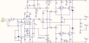
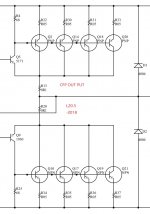
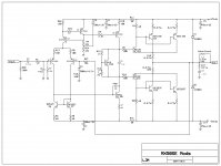
Please see the attached schematic to see how to add emitter resistors for current sharing in a paralleled CFP output. They must be in the emitter of each output.
I was following this thread and schematic...😕
MX50SE LJM 2015
Is this wrong...😕
I know the diodes are facing the wrong way
I fused my rails and my test speakers* when starting out with a brand new DIY amplifier. But I found that a very small fast fuse is needed to protect output transistors. And then while doing distortion measurements with REW I found that the small fuses heat and produce a little bit of distortion. (I was testing an ultra low distortion design.) I suppose some people will dispute that but you can actually measure it (on ultra low distortion designs).
*Why? My first speaker protection board from Ebay turned out to have a PCB layout error and it didn't work properly. [Don't assume that everything you buy online works, is designed correctly or is not a fake with a much lower real current/voltage or power rating... So it is very good that you bought the output transistors and capacitors from authorized distributors.]
So after thoroughly testing the new amplifier I put larger fuses in the rails but start with very small fast fuses. I also discovered that PTC will not protect anything on a power amplifier. (Not fast enough.)
Now I test my new amplifiers with a DIY dual power supply with current limiting. That has prevented a few
In your summary you did not mention the heatsink. Nice and big? Are you aware that you will want to run the amplifier for an hour or two while monitoring and readjusting the bias? (Before I assemble the chassis and put the cover on I do this several times over the first week or so of listening testing. Then I put in the larger rail fuses and put the cover on when I am sure everything is 100%.) Some people state that rail fuses are useless because they will not protect the output transistors. However I am also interested in reducing smoke and fire risk.
So I reversed engineered Gump's grocery Speaker Protection Board and it check ok with other schematics online.
I will keep an eye on the bias over time like you suggest.
The two heatsinks are the type that have the cooling fin's that will be facing outward. They make up the sides of the chassis. I think they are big enough.
One amp for each side. Kind of like this chassis...
Full aluminum WA17 class A AMP chassis power amplifier box DIY preamplifier enclosure|Shell & Body Parts| - AliExpress
I was following this thread and schematic...😕
MX50SE LJM 2015
Is this wrong...😕
I know the diodes are facing the wrong way
You mean the second schematic in post #4? I understand that the current sharing resistors must be in the emitter. (As they are in the parallel CFP LJM L12-2 and L20.5.) When one transistor conducts more emitter current than the other the voltage across the emitter sharing resistor increases raising the base voltage of that transistor relative to the one that is conducting less current. This opposes the in-balance in current and thus when the current sharing resistor is large enough you will achieve acceptable current sharing.
Consider if one transistor has a lower Vbe (either due to poor matching or due to higher temperature (or both)). That transistor will turn on at a lower Vbe and will draw more current than the other transistor at the same Vbe. That higher current will produce a higher voltage drop across the current sharing resistor which acts to raise the base voltage of that transistor and promote more equal current sharing.
And yes, the diodes are in backwards in that schematic.
Attachments
Last edited:
Yes that one... I see that the emitters are going straight to rail voltage?
And the 68 ohm res is connecting collector from Q10 and Q11 to the emitters of Q12-Q15? Not between rail and emitters😕
And the 68 ohm res is connecting collector from Q10 and Q11 to the emitters of Q12-Q15? Not between rail and emitters😕
Last edited:
So the collectors share one .2 ohm on each side but I see you put a .2 ohm on the emitters before they touch the rail voltage correct?
The 68 Ohm resistors will need to go to the rails and the emitter sharing resistors will need to go between the emitters and the rails.
I strongly recommend that you get the base (stock design) working well, debugged and well tested before changing it. [Have you done that already?]
I would never modify a new board/kit without thoroughly testing it first in the stock configuration.
I strongly recommend that you get the base (stock design) working well, debugged and well tested before changing it. [Have you done that already?]
I would never modify a new board/kit without thoroughly testing it first in the stock configuration.
Last edited:
Yes. That is how it is done on the L12-2 and L20.5 and it works properly. Follow the L12-2 schematic as that is actually quite close to a MX50SE modified to have two CFP pairs.
Did you measure the Vbe and hFE of the transistors you plan to pair together? Sometimes I get a nice set when I order however occasionally I have received a very mismatched set.
Did you measure the Vbe and hFE of the transistors you plan to pair together? Sometimes I get a nice set when I order however occasionally I have received a very mismatched set.
Well this seems like a fun to do mod... Will it be ok the use the 47 ohm base to emitter resistors? And should I use .2 ohm 5 watt on the emitter side to rails voltage?
Perfect... I did measure the digikey semi's and they are very close on the HFE within a few numbers of each other...
I will follow your advice and see how this goes. You explination was perfect in post #509.
Thanks so much... Saved me a headache...
Hope this helps others.
I'll be back...with good news I hope...Thanks
I will follow your advice and see how this goes. You explination was perfect in post #509.
Thanks so much... Saved me a headache...
Hope this helps others.
I'll be back...with good news I hope...Thanks
On the LJM 20.5 he uses 0.05 there. I used 0.12 (all I had) when I paralleled four CFP pairs.
So I would use 0.1 if you have it. If you don't then 0.2 will not cause a problem.
I wonder what the dependence (of distortion) is on emitter sharing resistor values on paralleled CFP outputs? Can anyone else comment and shed light on that?
So I would use 0.1 if you have it. If you don't then 0.2 will not cause a problem.
I wonder what the dependence (of distortion) is on emitter sharing resistor values on paralleled CFP outputs? Can anyone else comment and shed light on that?
Will it be ok the use the 47 ohm base to emitter resistors?
I think so at your rail voltages. I have seen 150 Ohms in LJM's L12-2 schematic, 68 Ohms in L20.5 and 47 Ohms in my MX50SE. Larger values reduce the dissipation in the drivers and I believe I have read recommendations to do that on the MX50SE. But right now I can not recall the particular posts to reference.
Perhaps someone else can comment/confirm if they should be switched to 68 Ohms (if you have them). There are lots of MX50SE owners on this forum so hopefully someone can confirm.

I'll be back...with good news I hope...Thanks
I hope so. Good luck! The following might help ensure success:
- Use a Dim Bulb Tester Powering Your Radio Safely with a Dim-bulb Tester
- Test each component before soldering. [I always do this with kits now.]
- After carefully checking the assembly put it aside and check it the next day carefully again before first power up.
- Build and test the stock design first before any mods. Give it a week or so of regular use and listening before mods.
- First power up with a current limited lab supply if you have it. LM317/LM337 dual supply is better than nothing and can prevent some experiences. You can check bias control, output offset and listen at surprising volumes with a simple current limited lab or LM317/LM337 dual supply. Current and power is much more limited (and quickly limited) with such a supply.
- Build and test your power supply alone first before connecting it to your new amplifier.
Before you power up the modified design you could even post clear pictures and others can try to spot issues before you power it up.
Last edited:
- Home
- Amplifiers
- Solid State
- LJM MX50 kit amp