Hello. I measured the quiescent current on my amplifier, something very small. Only 6-6. 5 mV. Input voltage per us, +-30 V. Does the quiescent current depend on the power supply voltage of the amplifier?
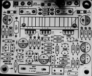
Specify, instead of this resistor (highlighted in yellow) to put a tuning one? And, here is this capacitor (highlighted in red) at 470 uf which, you need to increase to 1000 UF? What does it affect? And also, the remaining electrolytes per 100 uf (highlighted in green), is their increase necessary or not?

Specify, instead of this resistor (highlighted in yellow) to put a tuning one? And, here is this capacitor (highlighted in red) at 470 uf which, you need to increase to 1000 UF? What does it affect? And also, the remaining electrolytes per 100 uf (highlighted in green), is their increase necessary or not?
natural. There's no need to change. Just use it directly.Hello. I measured the quiescent current on my amplifier, something very small. Only 6-6. 5 mV. Input voltage per us, +-30 V. Does the quiescent current depend on the power supply voltage of the amplifier?
Specify, instead of this resistor (highlighted in yellow) to put a tuning one? And, here is this capacitor (highlighted in red) at 470 uf which, you need to increase to 1000 UF? What does it affect? And also, the remaining electrolytes per 100 uf (highlighted in green), is their increase necessary or not?
View attachment 927009
It's all designed in design.
Hello. I measured the quiescent current on my amplifier, something very small. Only 6-6. 5 mV. Input voltage per us, +-30 V. Does the quiescent current depend on the power supply voltage of the amplifier?
Specify, instead of this resistor (highlighted in yellow) to put a tuning one? And, here is this capacitor (highlighted in red) at 470 uf which, you need to increase to 1000 UF? What does it affect? And also, the remaining electrolytes per 100 uf (highlighted in green), is their increase necessary or not?
View attachment 927009
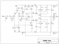
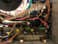
Hello... So I Installed a multi turn 2k pot in R-13 spot, the res you highlighted in yellow is R-12, should be R-13. I set mine to 6mv across the collectors, or you could clip on the the Emitters of Q-11 and 13. I replace C3 with a 1000uf/6.3v cap, did not harm anything. I think someone said it gives it a little more bass response. C-5 and C-14 I increased to 470uf/35v. My power supply is 18-0-18 so +-25 about. I lowered the voltage value of the cap's so they'd be at about 80% capacity, I left C-2,4,7 at 100uf/35v, and for C-5 and 14 a 470uf/50v cap wouldn't fit. The 35v is a smaller can size and fit no problem. I did double the final out put transistor's, PITA by the way, but it works perfect, does not get warm and is VERY powerful!!!
Attachments
Last edited:
Thanks...I'm not using that pre-amp shown, did not like it... I'm waiting for R.E. Project 97...should be here any day now. The sensitivity of these amps is almost too much. I may bring it down in half.
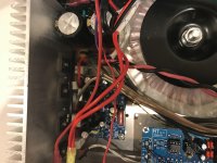
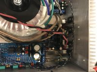
I got it like this. The housing is factory-built. However, the transformer is weak, from the music center. +-30.5 V and about 120W. Then I will order a round one for 250 W, 2*25 V.

As far as I'm going with it...
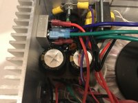
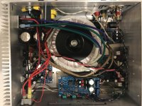
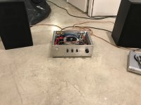
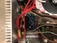
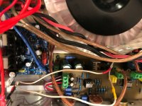
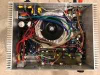
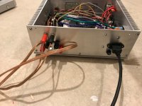
I know, I know, the chassis is very small. Originally I was building a 2.1 system but it didn't work out so well. So I decided to cram all this stuff into this chassis I already built It does work very well though. No hiss or hum, stays cold and plays plenty loud!
I need to look at the bias though as I think it needs more than 7mv, I do have double the outputs. I am using 18-0-18 300va and a pair of 10000uf 35v for filtering. I'm then feeding +-25 vdc to a regulator board to drop it to +-15 for the preamp.
Fun project and the next one will have a Larger Chassis with analog VU meters!
Thanks for all the info, mods and advice on this kit. 😎
I know, I know, the chassis is very small. Originally I was building a 2.1 system but it didn't work out so well. So I decided to cram all this stuff into this chassis I already built
It does work very well though. No hiss or hum, stays cold and plays plenty loud! I need to look at the bias though as I think it needs more than 7mv, I do have double the outputs. I am using 18-0-18 300va and a pair of 10000uf 35v for filtering. I'm then feeding +-25 vdc to a regulator board to drop it to +-15 for the preamp.
Fun project and the next one will have a Larger Chassis with analog VU meters!
Thanks for all the info, mods and advice on this kit. 😎
Attachments
-
 IMG_1070.jpg715.9 KB · Views: 231
 -
 IMG_1069.jpg728.6 KB · Views: 256
 -
 IMG_1068.jpg659.4 KB · Views: 224
 -
 IMG_1067.jpg699.6 KB · Views: 497
 -
 IMG_1066.jpg722.1 KB · Views: 491
 -
 IMG_1065.jpg742.2 KB · Views: 515
 -
 IMG_1064.jpg800.1 KB · Views: 531
 -
 IMG_1063.jpg902.7 KB · Views: 553
 -
 IMG_1071.jpg682.1 KB · Views: 206
All... I originally set the bias for 7mv and it sounded a little bad...distorted so I set bias for 14mv and it's night and day sound difference. Maybe because I've double the outputs is the reason for a higher bias voltage needed. I've had it playing at a decent volume for an hour or so and it just gets luke warm.
DC offset... Left channel=0.008, Right channel=0.000
With 1000hz input tone and output into an 8ohm dummy load, it clips at around 15.5 vrms. Not much power when you do the math. I think with a higher voltage transformer this would increase. All in All the sound Q is great.
Now to build an L20SE set. This will have +-43 vdc.
Hello, I am about to buy LJM kit for MX50 SE from aliexpress;
I would choose the sanken version with 2SC3264/2SA1295 provided,
but I have some questions that hold me back from proceeding
is there any chance to receive fake sanken ?
is there really audible differences with Kec B817/D1047 ?
with power supply +- 34V, would I achieve 80W RMS on 8 ohm ?
thanks
I would choose the sanken version with 2SC3264/2SA1295 provided,
but I have some questions that hold me back from proceeding
is there any chance to receive fake sanken ?
is there really audible differences with Kec B817/D1047 ?
with power supply +- 34V, would I achieve 80W RMS on 8 ohm ?
thanks
I might suggest getting the B817/D1047 MX50SE version (which I worry might not be genuine KEC) and then ordering genuine Sanken like 2SC6145 and 2SA2223 from the authorized distributor Digikey so that you know they are genuine.
If you are truly using 8 Ohms and truly +/- 34V DC then MX50SE is a good choice. My own experience was that my speakers (sold as 8 Ohms) are actually 4 Ohms so now I only get kits with two pairs of outputs (or more) like the L12-2 or L20SE.
If you are truly using 8 Ohms and truly +/- 34V DC then MX50SE is a good choice. My own experience was that my speakers (sold as 8 Ohms) are actually 4 Ohms so now I only get kits with two pairs of outputs (or more) like the L12-2 or L20SE.
many thanks for answers
kits on aliexpress have 2SC3264/2SA1295,
wich are not currently available on digikeys 🙁
2SC6145 and 2SA2223 are.. it's the same ?
kits with sanken 2SC3264/2SA1295, with green board, seems
different from those with kec transistor, with blue board.
Is it the same just changing type of transistor,
or also components/schema must be changed ?
Last question, my speakers are 8 ohm, they only go down
to 6 ohm at about 150 hertz, so +-34 would be fine.
However they are not so sensitive, so they require power,
can I achieve at least 80 W rms ?
My understanding is that 2SC3264/2SA1295 are out of production for quite some time and that what you get "online" is quite likely to be fake. Fake output devices, capacitors and fake op-amps are a plague on Ebay & AliExpress.
The 2SC6145 and 2SA2223 pair are one of the best similar Sanken devices that are still available. Their SOA is quite a bit better than the B817/D1047.
That said I am not sure the MX50SE is aimed at low sensitivity speakers. I tend to be conservative and for a solid and reliable 100W I would suggest one of the bigger amps. I view the MX50SE as a smaller amp. The L12-2 is CFP like the MX50SE and had quite a good following. The L20SE is not a CFP output but is a similar "blameless" overall design. Both the L12-2 and L20SE should have no trouble long term with lower sensitivity speakers and 80W.
Perhaps someone else can comment but my general impression of the MX50SE is more towards lower output powers. Then again with Sanken outputs and a suitable heatsink it might be ok. Hopefully someone else can add their experiences.
First, thank you for useful contribution to this conversation and elsewhere. I do appreciate that.My understanding is that 2SC3264/2SA1295 are out of production for quite some time and that what you get "online" is quite likely to be fake. Fake output devices, capacitors and fake op-amps are a plague on Ebay & AliExpress.
>snip>
Regarding the selection of devices it is impossible to find the "originals" because they're discontinued a long time ago by the original producers, but distinction should be made between outright fakes and normal generic devices which are still in production elsewhere. Notable among them is ISC.
I purchase kits but all semiconductors from the kit end up in the bin, the most of capacitors too. Then I purchase larger number of devices and make selection. Perhaps in the future I will dump everything except the board because the recent L20.5 had rather bad resistors.
For example, I have replaced the D669 and B649 from all LJM kits with matched SA1220 and SC2690 (generic ISC products). This has reduced noise substantially and persistent 50MHz parasitic has vanished after the replacement. Also, without the signal at the output the scope shows much cleaner output, a straight narrow line. This replacement made substantial difference. Though, it should be noted that SA1220 and SC2690 have a bit lower value of collector current (Ic=1.2A vs. 1.5A). Also, these must be isolated with mica.
Another good alternative though a bit more expensive are NTE 373 and NTE 374 (Cob 14pF, product of NTE inc, Bloomfield, NJ). These have essentially identical values compared to D669 and B649
Also in the LJM L20.5 kit they have inappropriate 1549A and 4370A which should be replaced with audio grade SA1930 and SC5171
I have wondered about ISC but they do not seem to be carried by any distributors in the US. When I was looking at ordering them from Europe the shipping cost was prohibitive.
What do you think about the newer Toshiba TTA004 and TTC004 in place of the D669 and B649? (That is what I used from the authorized distributors here, Mouser & Digikey.)
Also when I looked up 2SC5171 on Mouser it is also obsolete but Mouser suggested TTC004 as a "similar product".
Finally what are the issues you noted with the resistors on the L20.5?
Company History-Inchange Semiconductor Company (ISC) ?????????????isc › about
... in the large industrial park of the Wuxi-New-District,Jiangsu province, China.
Produces replicas of discontinued semiconductor devices. Does not guarantee compliance and does not have any liability for damage.
General compliance with basic specifications only.
Toshiba is on the verge of bankruptcy?, problems with management.
Biden wants to organize the production of semiconductors in the United States.
Last edited:
- Home
- Amplifiers
- Solid State
- LJM MX50 kit amp