Hi,
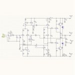
Is the shematic good?😕
Thanks,
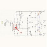
Buddy, be aware that your schematic is wrong.
Look at this:
https://i.ibb.co/Bnsb8mR/Schema-effettivo-2.jpg
Last edited:
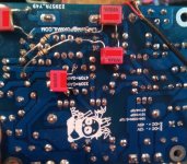
On all versions of the board that I have, the silkscreened part symbol for the two components labelled "104" is different. One has rounded corners, just like the symbol for what are clearly other capacitors, but the other, next to the 10R 2W resistor, has square corners. Are these both indeed capacitors, or is the latter something else, such as an inductor?
Thanks!
Thanks!
I recently ordered two sets of mx50se on e-ba and the first set (of kits it turned out) seem genuine from pictures way up the thread. Which was interesting because the pictures on the listing suggested I would get way off fakes. The second set had the right picture but these boards seem fake unless there was an update to the design.


Some of the components in my kits did seem a bit different than the ones in ljm's post like the 105 cap in the center was a 106 (labelled such as well) I used c5200/a1943 genuine instead of the kit chips.
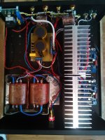
Sorry about the lighting on the board in my amp.
Edit: I just noticed it's a single sided pcb. It does produce sound, when tested on my bench.
Some of the components in my kits did seem a bit different than the ones in ljm's post like the 105 cap in the center was a 106 (labelled such as well) I used c5200/a1943 genuine instead of the kit chips.
Sorry about the lighting on the board in my amp.
Edit: I just noticed it's a single sided pcb. It does produce sound, when tested on my bench.
Last edited:
Are you mainly asking about the older design with the ferrite at the input? There was an older design like that.
No I was comparing with the picture ljm posted somewhere else, a search turned it up... So I guess my question becomes is the single sided board in my pic an OLDER version, as it is marked 2017? Or a knockoff?

Hi,
Ca the output transistor s be replaced with MJ15003/MJ15004?
Are changes to the schematic needed?
Thanks,
Ca the output transistor s be replaced with MJ15003/MJ15004?
Are changes to the schematic needed?
Thanks,
No I was comparing with the picture ljm posted somewhere else, a search turned it up... So I guess my question becomes is the single sided board in my pic an OLDER version, as it is marked 2017? Or a knockoff?
View attachment 1026049
Attachments
Please help us and someone could clarify the differences between the various versions of the LJM MX50 amp kit - we've seen for sale versions 6.1 and 6.3. More recently the SE version. Does the transistors 5401, 5551, 1815 and with 2SB649 & 2SD669 plus power Sanken 2SA1186 and 2SC2837 as an amplifier providing good fidelity music reproduction?
Attachments
Hello friends,
I have two of these kits and I'm going to assemble them...
1. Can anyone tell me what kind of power I get on 4 and 8 ohm? I have 2 transformers 2x25V 225W
2. I would also be curious to see a direct comparison of MX50 SE vs My_Ref Fremen Edition 🙂
Do you recommend to use output transistors from the kit (KTB817/KTD1047) or replace with better ones?
My favourite: 2SA1943/2SC5200 (On Semi)
Thank You!
Hey,i think in 4 ohm you get prob 100w or so with 25v and 8 ohm 40w or so.Hello friends,
I have two of these kits and I'm going to assemble them...
1. Can anyone tell me what kind of power I get on 4 and 8 ohm? I have 2 transformers 2x25V 225W
2. I would also be curious to see a direct comparison of MX50 SE vs My_Ref Fremen Edition 🙂
Do you recommend to use output transistors from the kit (KTB817/KTD1047) or replace with better ones?
My favourite: 2SA1943/2SC5200 (On Semi)
Thank You!
But i dont get it what you are doing with 2 transformers??For stereo or what?
Better transistors are better,i use 2sc too and works very good.
I power my kit with 62v and 560w transformer!!But you need to fix the BIAS!!And you need good transistors!
Yes you can put that transistors,technically!!Physical you need some wires becouse that is a To-3 transistor!Hi,
Ca the output transistor s be replaced with MJ15003/MJ15004?
Are changes to the schematic needed?
Thanks,
And you need to fix the BIAS!
This are the new version.No I was comparing with the picture ljm posted somewhere else, a search turned it up... So I guess my question becomes is the single sided board in my pic an OLDER version, as it is marked 2017? Or a knockoff?
View attachment 1026049
Hello.
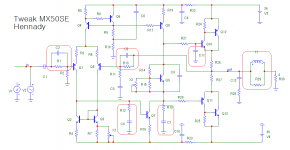
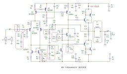
I will present my version of the Tweak amplifier from the MX50SE kit
scheme:
The sound of this scheme is mainly determined by the miller correction, which reduces the linearity of the scheme, while greatly reducing the depth of NFB at a frequency of 20 kHz, which ultimately affects the sound quality: muted highs, a blurry stereo base, the soundstage is practically not drained, we can talk about any sound detail not necessary at all.
And so the tweak elements with progressive correction:
this is the circuit at the inputs of the input differential stage R1C2 and R13C5
the main voltage gain of the amplifier is provided by the transistor Q7, around it the main correction is obtained - this is the circuit at the input R12C4 and at the output R19C7,
also added capacitor C11 to the base of the VC Q8 driver - it is needed to stabilize Fed when the VC is operating in class AB,
a Boucher coil was added - its cutoff frequency turned out to be 45 kHz, the reason is in the VC on the Shiklai assembly, which works in class AB, due to which a large tail of harmonics is obtained at the HF, and with increasing amplitude, the growth increases, the Boucher coil limits this spectrum and, in fact, to The output is no longer an ascending but a descending spectrum.
The time constant of the Boucher coil correlates according to the Boucher equation with the R28C12 Zobel chain, and exactly the same with the value of the time constant of NFB circuit R13C5, and taking into account the gain Ku with a chain at the input R1C2.
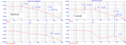
The result of this correction is the maximum linearity of the input stage, the uniformity of the depth of the feedback in the audio frequency band, the harmonic coefficient does not depend on the frequency, even taking into account the change in the spectrum with increasing frequency, the distortion at an output power of 98 watts at 4 ohms as at a frequency of 1 kHz - 0 .02% , at a frequency of 20kHz - 0.024%
The frequency response before and after the tweak, it was possible to achieve linearity no worse than +/-3 dB before NFB coverage:
P.S. trimmer X2 added - to increase the quiescent current of the VC to 150mA (in the Market version, the VC current is 30mA), the trimmer X1 adjusts the voltage at the output of the amplifier at a level of less than 1mV.
the sound is generally good, the soundstage has appeared, the sound is detailed, the voice is not tight, the echo has become the norm in the sound....
For correction, film film capacitors were used, except for C11, due to its insignificant denomination, it is ceramic.
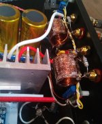
some photos of practical implementation:
I will present my version of the Tweak amplifier from the MX50SE kit
scheme:
The sound of this scheme is mainly determined by the miller correction, which reduces the linearity of the scheme, while greatly reducing the depth of NFB at a frequency of 20 kHz, which ultimately affects the sound quality: muted highs, a blurry stereo base, the soundstage is practically not drained, we can talk about any sound detail not necessary at all.
And so the tweak elements with progressive correction:
this is the circuit at the inputs of the input differential stage R1C2 and R13C5
the main voltage gain of the amplifier is provided by the transistor Q7, around it the main correction is obtained - this is the circuit at the input R12C4 and at the output R19C7,
also added capacitor C11 to the base of the VC Q8 driver - it is needed to stabilize Fed when the VC is operating in class AB,
a Boucher coil was added - its cutoff frequency turned out to be 45 kHz, the reason is in the VC on the Shiklai assembly, which works in class AB, due to which a large tail of harmonics is obtained at the HF, and with increasing amplitude, the growth increases, the Boucher coil limits this spectrum and, in fact, to The output is no longer an ascending but a descending spectrum.
The time constant of the Boucher coil correlates according to the Boucher equation with the R28C12 Zobel chain, and exactly the same with the value of the time constant of NFB circuit R13C5, and taking into account the gain Ku with a chain at the input R1C2.
The result of this correction is the maximum linearity of the input stage, the uniformity of the depth of the feedback in the audio frequency band, the harmonic coefficient does not depend on the frequency, even taking into account the change in the spectrum with increasing frequency, the distortion at an output power of 98 watts at 4 ohms as at a frequency of 1 kHz - 0 .02% , at a frequency of 20kHz - 0.024%
The frequency response before and after the tweak, it was possible to achieve linearity no worse than +/-3 dB before NFB coverage:
P.S. trimmer X2 added - to increase the quiescent current of the VC to 150mA (in the Market version, the VC current is 30mA), the trimmer X1 adjusts the voltage at the output of the amplifier at a level of less than 1mV.
the sound is generally good, the soundstage has appeared, the sound is detailed, the voice is not tight, the echo has become the norm in the sound....
For correction, film film capacitors were used, except for C11, due to its insignificant denomination, it is ceramic.
some photos of practical implementation:
Attachments


Hello.
I will present my version of the Tweak amplifier from the MX50SE kit
scheme:
The sound of this scheme is mainly determined by the miller correction, which reduces the linearity of the scheme, while greatly reducing the depth of NFB at a frequency of 20 kHz, which ultimately affects the sound quality: muted highs, a blurry stereo base, the soundstage is practically not drained, we can talk about any sound detail not necessary at all.
And so the tweak elements with progressive correction:
this is the circuit at the inputs of the input differential stage R1C2 and R13C5
the main voltage gain of the amplifier is provided by the transistor Q7, around it the main correction is obtained - this is the circuit at the input R12C4 and at the output R19C7,
also added capacitor C11 to the base of the VC Q8 driver - it is needed to stabilize Fed when the VC is operating in class AB,
a Boucher coil was added - its cutoff frequency turned out to be 45 kHz, the reason is in the VC on the Shiklai assembly, which works in class AB, due to which a large tail of harmonics is obtained at the HF, and with increasing amplitude, the growth increases, the Boucher coil limits this spectrum and, in fact, to The output is no longer an ascending but a descending spectrum.
The time constant of the Boucher coil correlates according to the Boucher equation with the R28C12 Zobel chain, and exactly the same with the value of the time constant of NFB circuit R13C5, and taking into account the gain Ku with a chain at the input R1C2.
The result of this correction is the maximum linearity of the input stage, the uniformity of the depth of the feedback in the audio frequency band, the harmonic coefficient does not depend on the frequency, even taking into account the change in the spectrum with increasing frequency, the distortion at an output power of 98 watts at 4 ohms as at a frequency of 1 kHz - 0 .02% , at a frequency of 20kHz - 0.024%
The frequency response before and after the tweak, it was possible to achieve linearity no worse than +/-3 dB before NFB coverage:
P.S. trimmer X2 added - to increase the quiescent current of the VC to 150mA (in the Market version, the VC current is 30mA), the trimmer X1 adjusts the voltage at the output of the amplifier at a level of less than 1mV.
the sound is generally good, the soundstage has appeared, the sound is detailed, the voice is not tight, the echo has become the norm in the sound....
For correction, film film capacitors were used, except for C11, due to its insignificant denomination, it is ceramic.
some photos of practical implementation:
I have done similar experiments. As a result, these capacitors will degrade the performance of the amplifier.Hello.
I will present my version of the Tweak amplifier from the MX50SE kit
scheme:
The sound of this scheme is mainly determined by the miller correction, which reduces the linearity of the scheme, while greatly reducing the depth of NFB at a frequency of 20 kHz, which ultimately affects the sound quality: muted highs, a blurry stereo base, the soundstage is practically not drained, we can talk about any sound detail not necessary at all.
And so the tweak elements with progressive correction:
this is the circuit at the inputs of the input differential stage R1C2 and R13C5
the main voltage gain of the amplifier is provided by the transistor Q7, around it the main correction is obtained - this is the circuit at the input R12C4 and at the output R19C7,
also added capacitor C11 to the base of the VC Q8 driver - it is needed to stabilize Fed when the VC is operating in class AB,
a Boucher coil was added - its cutoff frequency turned out to be 45 kHz, the reason is in the VC on the Shiklai assembly, which works in class AB, due to which a large tail of harmonics is obtained at the HF, and with increasing amplitude, the growth increases, the Boucher coil limits this spectrum and, in fact, to The output is no longer an ascending but a descending spectrum.
The time constant of the Boucher coil correlates according to the Boucher equation with the R28C12 Zobel chain, and exactly the same with the value of the time constant of NFB circuit R13C5, and taking into account the gain Ku with a chain at the input R1C2.
The result of this correction is the maximum linearity of the input stage, the uniformity of the depth of the feedback in the audio frequency band, the harmonic coefficient does not depend on the frequency, even taking into account the change in the spectrum with increasing frequency, the distortion at an output power of 98 watts at 4 ohms as at a frequency of 1 kHz - 0 .02% , at a frequency of 20kHz - 0.024%
The frequency response before and after the tweak, it was possible to achieve linearity no worse than +/-3 dB before NFB coverage:
P.S. trimmer X2 added - to increase the quiescent current of the VC to 150mA (in the Market version, the VC current is 30mA), the trimmer X1 adjusts the voltage at the output of the amplifier at a level of less than 1mV.
the sound is generally good, the soundstage has appeared, the sound is detailed, the voice is not tight, the echo has become the norm in the sound....
For correction, film film capacitors were used, except for C11, due to its insignificant denomination, it is ceramic.
some photos of practical implementation:
Not promotion.
I won't lie to you. Because these capacitors are not worth money.
If you want to improve performance. The 330r resistance can be changed to 470 ohms. It will significantly improve performance.
But the volume will decrease.
But I don't think you will agree with me.
No problem. DIY needs personalization. 👽
It cannot degrade the performance that increases the linearity of the amplifier to the coverage of NFB.
for modern sound sources, even 470 ohms is not enough, I set 680 ohms, so much better ...
the capacitance of the capacitors in my correction is in fact much less than the capacitance of the capacitor in Miller's correction., and most importantly, in my correction, the output stage is controlled by current at high frequencies, and in Miller's correction this is not possible, because Miller's correction leads to sound degradation.
Now the sound is ok, because I got rid of the miller correction that stifles the sound of the amplifier ... Practical implementation of this is confirmation ...
In fact, I used this RC filter on mx50x2.It cannot degrade the performance that increases the linearity of the amplifier to the coverage of NFB.
for modern sound sources, even 470 ohms is not enough, I set 680 ohms, so much better ...
the capacitance of the capacitors in my correction is in fact much less than the capacitance of the capacitor in Miller's correction., and most importantly, in my correction, the output stage is controlled by current at high frequencies, and in Miller's correction this is not possible, because Miller's correction leads to sound degradation.
Now the sound is ok, because I got rid of the miller correction that stifles the sound of the amplifier ... Practical implementation of this is confirmation ...
The cob capacitance can be reduced to 10PF. Even removal has no effect.
I use 100r resistor and 12PF capacitor.
You've done a little too much. You used 3 sets of RC filters.
But your idea is a good try.
Because I have the same idea. If you can, you can specifically talk about the data of these resistors and capacitors.
Sorry, I'm too busy sometimes. Otherwise, I will try it again.
The RC filter time constants you show are not sufficient to fully correct the phase at the unity gain frequency.
thank you for appreciating my version of the progressive amplifier correction.
three sets of RC filters have less effect on the sound than a single 100 picofarad capacitor in the Miller correction circuit, because its actual capacitance in the driver load multiplied by the non-NFB gain, which is a lot.
P.S. this is not my only project of recorrecting vintage circuitry with spoiled sound using Miller correction.
Yes, the parameters of the RC filters are not shown, because I think that they should be agreed with the author of this kit - these RC filters translate this circuit to a higher sound quality level.
In fact, I was confused.I recently ordered two sets of mx50se on e-ba and the first set (of kits it turned out) seem genuine from pictures way up the thread. Which was interesting because the pictures on the listing suggested I would get way off fakes. The second set had the right picture but these boards seem fake unless there was an update to the design.
View attachment 1025882View attachment 1025883View attachment 1025884
Some of the components in my kits did seem a bit different than the ones in ljm's post like the 105 cap in the center was a 106 (labelled such as well) I used c5200/a1943 genuine instead of the kit chips.
Sorry about the lighting on the board in my amp.
Edit: I just noticed it's a single sided pcb. It does produce sound, when tested on my bench.
From the photos. It should indeed be produced by me. But this is a product before 2017. Because I later found that the cost of double-sided PCB is almost the same. So I used a double-layer PCB. After all, it is more durable because the copper skin is not easy to fall off.
But you shouldn't be able to buy it in 2022.
By testing the correction of the previous version, and decided to completely abandon the differentiating correction circuits, the reason is in the output stage of the Shiklai assembly, because of its operation, the stability margin changed from heating this assembly.
See attachment:
minimum initial current Bias output assembly Shiklai 90mA, adjustable by adding a resistor R15
C1 increased to 10uF 100V (metal film)
added integrating circuit to R2C2 input
added accelerating capacitor C6 (47pF) in parallel with R14
the integrating circuit R13C4 is also used at the input of the second voltage amplification stage
the input of the output stage is shunted by a rather large capacitor C7, however, the unity gain for the negative feedback circuit is 2.5 MHz, which is not bad.
gain without negative feedback is 83.5dB with non-linearity 20Hz - 20kHz is only +/-2.5dB, I think this is a very linear gain, with the standard Miller correction, this result cannot be achieved.
The sensitivity of the amplifier is reduced to 1.6V (RMS) by increasing the resistor R12 to 680 ohms, and the gain is now 23dB.
Also added L1 Bushe coil at the output of a very large denomination of 10 uH and a 10 ohm resistor - this is necessary to limit the spectrum до 45kHz at the output of the amplifier and overprotect the NFB circuit from the capacitive nature of the load of the speaker system.
according to the results of listening, this option turned out to be the best, light and clear high-frequency sounds, good localization of performers and a good soundstage.
The correction option indicated in the attachment is practically implemented by hanging installation.
Attachments
Last edited:
Hi Hennady,according to the results of listening, this option turned out to be the best, light and clear high-frequency sounds, good localization of performers and a good soundstage.
Have you measured the impact of the proposed changes?
... Or you have based your judgement purely on your subjective impression?
Have you considered the impact of the placebo-effect?
Over the past week I have repeated the build from the scratch, starting from brand new kit from components in the kit only. I have measured every single component: All components from the kit are just fine. I have made no changes at all. I have measured all significant parameters and have concluded that the amplifier has performed exactly as declared.
Why should we fix what ain't broke?
LJM is a qualified and recognized expert who has developed this amplifier and improved it gradually and the amplifier in the present form can be considered as a mature and reliable product.
Sincerely!
Last edited:
- Home
- Amplifiers
- Solid State
- LJM MX50 kit amp