i'm refering to signal !!!ground lift not 230v earthing my friend.If this is the way that reading the books my advise is to buy a ready commercial amplifier....sorry.
i'm refering to signal !!!ground lift not 230v earthing my friend.If this is the way that reading the books my advise is to buy a ready commercial amplifier....sorry.
You are contradicting yourself?
In your previous post you said;
It's no matter of noise,but for distortion and interference.You converted a dual power supply to mono.About the 22omhs resistor it is a safety one not a ground lift,the power gnd is connected with signal gnd with the thin wire all the time.Signal ground lift resistor is a very bad thing.Star ground must be at the big capacitors for all constructions.
Your post implied you were referring to the safety ground (earth).
So you've changed your mind now then?
Anyway - I didn't come here to argue.
This is going nowhere, and I think I have made my point.
Afternoon, Can I try people with a power supply issue for these MX50SE boards?
I'm trying to repair this:
1975 100w Power Amp Schematic
My hope was by stripping out the old, and amusingly repaired many, many times, power amp board I could use the MX50SE as a drop in replacement. The nominal 42v + and - rails seems within range that the board can take.
I stripped everything out, have the ground and + and - voltages ready to attach to the board. Unfortunately on my meter I'm reading input AC 257 volt, transformer AC +/- 40, DC +/- 55.
Questions are how likely is an RSPRO-RS12 meter to be reading over?
Could this just be an effect of having no load at all on the power supply?
If the numbers are true is there an easy-ish way to drop those DC voltages?
I ask because I have 6 of these to repair and the board is a near ideal solution if the power supply can be used. I also assume that the power supplies may have different outputs per amplifier.
I'm also wondering if poor power supply quality control was the reason why WEM amps of this period had a bad reputation for frying themselves.
Choices are 110, 220 and 240. The pin is firmly in 240.
There is a possibility it was mis-wired at the factory and the 220 from the transformer was wired to the 240 position
which would push voltages up. I will try it on 220 and see what I get.
However the fact that my house is reading nearly 260 VAC suggests either a generous home supply or the meter.
Wikipedia claims "nominal supply voltage is 230 V +10%/−6%" = 256 VAC.
Last edited:
<snip>
However the fact that my house is reading nearly 260 VAC suggests either a generous home supply or the meter.
Wikipedia claims "nominal supply voltage is 230 V +10%/−6%" = 256 VAC.
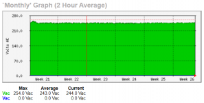
I'm in the UK and my mains (monitored via a UPS) has been as high as 255v but seems to average about 243v
So depending on where you are, your mains doesn't seem unusually high.
However if it's always that high I'd raise the issue with your electricity company.
The attached graph is my average mains over a period of a month.
Attachments
I about to set the current on my build,Should the voltage across each of the 0,22 ohm resistors be 10mv or should it be more??
10 mV corresponds to 50 mA. If you put more, heating will increase. Sound quality will not improve.
Last edited:
Been searshing but no go.
Is there a thread about LJM L7 Mosftet amp?
Anyone know?
L7 MOSFET DIY amp kit by LJM
L7 MOSFET amp test 20-350kHz
Wattage claims from L7 eBay amplifier
There are a few others as well.
If you search Google using this search term: ljm l7 mosfet amp diyaudio site:www.diyaudio.com
You'll see more results.
10 mV corresponds to 50 mA. If you put more, heating will increase. Sound quality will not improve.
Hello. I set the quiescent current to 80 mA, sounding great with excellent development of high frequencies and tight bass. Transistors 5200/1943 at the output.
Hello! I've built the amplifier with modifications to the choice of spare parts. I used better transistor capacitors and resistors. I placed bias trimer. I pumped the amplifier with + - 40 volts. The result is fantastic!
Hello madel88,
I know your post is three years old but can you confirm that you used Polystyrene, PW and FW capacitors on your MX50 SE mods?
Are the choices because you built from bare boards or specific upgrade choices? Or just had those values and series?
Would you still pick those if you did it again?
MX50SE These are the capacitor models currently in use
50V100UF *10 nichicon VR /VZ Filter capacitor
16V470UF *2 nichicon HV Signal capacitance
3.3UF MKP PANASONIC Signal capacitance
I don't recommend replacing any capacitors.
These are the best capacitors.
Other types of filter electrolytic capacitors are sometimes used.
It depends on whether the supplier has a ready supply.
Maybe there will be Rubycon Nippon Samsung. But the current one is Nichicon
Last edited:
Hello madel88,
I know your post is three years old but can you confirm that you used Polystyrene, PW and FW capacitors on your MX50 SE mods?
Are the choices because you built from bare boards or specific upgrade choices? Or just had those values and series?
Would you still pick those if you did it again?
MX50SE These are the capacitor models currently in use
50V100UF *10 nichicon VR /VZ Filter capacitor
16V470UF *2 nichicon HV Signal capacitance
3.3UF MKP PANASONIC Signal capacitance
I don't recommend replacing any capacitors.
These are the best capacitors.
Hello friends, how are you? I would like my mx50 to work in class A at low power (1 to 10watts). I have a large heatsink I believe is sufficient for the mx50 in class A. The voltage on it is 24.5vdc. I have very sensitive speakers (95db / 1watts) so I don't need a lot of power to have a high volume. What modifications could I make to make it operate in class A? Would it be to increase only the bias?
Yes, I have done this with 26V and 0,4A with the Sanken outputs. It really cleans up the distortion spectrum at low output levels. You might be able to increase Iq more if you have really good cooling. I would also recommend a bit higher capacitance on the input cap, 10uF or so if your speakers can play low bass.
Yes, I have done this with 26V and 0,4A with the Sanken outputs. It really cleans up the distortion spectrum at low output levels. You might be able to increase Iq more if you have really good cooling. I would also recommend a bit higher capacitance on the input cap, 10uF or so if your speakers can play low bass.
Oh yes, I made this change, because I felt little presence of bass in the system. My doubt is: I adjust the bias with a multimeter probe on one side of the resistor and the other end on the emitter of the NPN transistor. As this amplifier has CFP output, I was wondering if I do it the same way or if there is another way to adjust the bias?
Last edited:
I just added the trimmer in the bias circuit, and measured the current with an A-meter on the supply. I also did some distortion measurements, and it seemed there was diminishing return increasing the current above 0,4A.
I have also checked this amp with square wave in and the HF capacitors on input and output disconnected, and it has some strange peaking behavior on the positive flank. The peaking increases with output level/current. Same behavior on the L12-2, seems something is not 100% right with the stability.
I have also checked this amp with square wave in and the HF capacitors on input and output disconnected, and it has some strange peaking behavior on the positive flank. The peaking increases with output level/current. Same behavior on the L12-2, seems something is not 100% right with the stability.
- Home
- Amplifiers
- Solid State
- LJM MX50 kit amp