I tried exactly that type, but I liked the sound with linear PS better. They create a lot of EMI, both radiated and as ripple on the output. I made a separate metal shield around the PS, and used CM chokes on the output from the SMPS. A lot of HF was still visible on the amp output. After I switched to transformer, and sound was a little bit better in the treble area.
I simply have to check this thread CAREFULLY as I just (today) dug up my MX50, bought a simple wooden box that will house them for a period of time (eternity 🙄).
Have a 2x36V transformer and some bigger caps.
Need the power to make new speakers sing for me. 3W of pure tube class A is a bit too not enuff.
Have a 2x36V transformer and some bigger caps.
Need the power to make new speakers sing for me. 3W of pure tube class A is a bit too not enuff.
I simply have to check this thread CAREFULLY as I just (today) dug up my MX50, bought a simple wooden box that will house them for a period of time (eternity 🙄).
Have a 2x36V transformer and some bigger caps.
Need the power to make new speakers sing for me. 3W of pure tube class A is a bit too not enuff.
.. actually if they are really 36VAC, it means that in direct current they are almost 48 / 49VDC ... a little too many for this PCB
I did a small modification to a pair of these today. I have been a little bit unhappy about the mid-treble, giving me listening fatigue. Maybe it could be described as sounding bright. I have one amp where I run these boards on 26V and high bias. Separate transformer secondaries & rectifiers for each channel, Sanken outputs, some better capacitors installed (input/feeback/rail decoupling), temperature controlled fan cooling etc This makes pretty good sound, but there is still something that makes me prefer my JLH class A.
Measurements are good, with really low distortion levels, and no signs of oscillation etc, so I have no logical explanation to why I prefer the JLH that actually measures worse.
Ok, there is distortion spectrum differences, but with distortion more than 100dB under signal level, and disappearing in to the noise at normal listening levels, I think that should not be audible. The measured JLH distortion is also in the -90dB area.
Anyway, I did a small test today and tried to replace the emitter resistors for the outputs. The ones that came with all boards I have are 0,15ohm, and many schematics and PCB markings seem to indicate 0,22ohm. So, I soldered in some 0,27ohm resistors I found, and did some measurements and adjustments. I ended up with abt 0,5A Iq, a little bit lower than with the 0,15ohm resistors when I had abt 0,7A. (adjusted looking at distortion spectrum & level)
When it comes to distortion the differences were minor. With sine input, the even harmonics were a little bit higher with the new resistors (but odd harmonics still dominate), and with multitone input (ARTA) there was a slight decrease in the 'distortion floor' in the treble area (or increase in signal to noise if you like). Two tone IMD very low and similar in both cases. Everything at very low levels in the -100dB area, so I doubt it would be audible. I had to crank up to several watts to even see the distortion over noise. I normally prefer to measure at low levels (abt 1-2W), but here I'm forced to crank it up more to see anything above the noise floor.
Anyway, I think the amp sounds a little bit 'smoother' now, with the larger resistor values. No explanations, just a subjective feeling..
So, if people feel like experimenting, this could be worth trying.
I did a small modification to a pair of these today. I have been a little bit unhappy about the mid-treble, giving me listening fatigue. Maybe it could be described as sounding bright. I have one amp where I run these boards on 26V and high bias. Separate transformer secondaries & rectifiers for each channel, Sanken outputs, some better capacitors installed (input/feeback/rail decoupling), temperature controlled fan cooling etc This makes pretty good sound, but there is still something that makes me prefer my JLH class A.
Measurements are good, with really low distortion levels, and no signs of oscillation etc, so I have no logical explanation to why I prefer the JLH that actually measures worse.
Ok, there is distortion spectrum differences, but with distortion more than 100dB under signal level, and disappearing in to the noise at normal listening levels, I think that should not be audible. The measured JLH distortion is also in the -90dB area.
Anyway, I did a small test today and tried to replace the emitter resistors for the outputs. The ones that came with all boards I have are 0,15ohm, and many schematics and PCB markings seem to indicate 0,22ohm. So, I soldered in some 0,27ohm resistors I found, and did some measurements and adjustments. I ended up with abt 0,5A Iq, a little bit lower than with the 0,15ohm resistors when I had abt 0,7A. (adjusted looking at distortion spectrum & level)
When it comes to distortion the differences were minor. With sine input, the even harmonics were a little bit higher with the new resistors (but odd harmonics still dominate), and with multitone input (ARTA) there was a slight decrease in the 'distortion floor' in the treble area (or increase in signal to noise if you like). Two tone IMD very low and similar in both cases. Everything at very low levels in the -100dB area, so I doubt it would be audible. I had to crank up to several watts to even see the distortion over noise. I normally prefer to measure at low levels (abt 1-2W), but here I'm forced to crank it up more to see anything above the noise floor.
Anyway, I think the amp sounds a little bit 'smoother' now, with the larger resistor values. No explanations, just a subjective feeling..
So, if people feel like experimenting, this could be worth trying.
Hi,
on the PCB, in relation to emitter resistance it is written from 0.1 to 0.22 ohms, they put in the 0.15 ohms resistor kit, a middle ground ... What gain do you use in your PCB? 330ohm 31 gain or 470ohm 22 gain? I think the gain is a little too much, in fact I put 470ohm, I think I will go up to 520ohm .... try to adjust the gain .
I think it's the lower gain. I have the lower gain resistors on most of my boards since I feed them directly from sound card. Not 100% sure about these though.
After some more listening, I also have the impression that the bass is less 'dynamic and precise' with the 0,27ohm resistors. Seems like a bit of trade-off between bass and mid/treble. Maybe 0,22ohm would be a god compromise.
I still prefer the JLH though..
After some more listening, I also have the impression that the bass is less 'dynamic and precise' with the 0,27ohm resistors. Seems like a bit of trade-off between bass and mid/treble. Maybe 0,22ohm would be a god compromise.
I still prefer the JLH though..
Last edited:
.. today I tested three of these Amplifier Kits, I found a resting current BIAS, on all three, of 110mA !!!! ... after a few seconds from turning on .... the heat sink is already very hot ... as suggested by Noise diyAudio Member, I replaced the 1K resistor on the emitter with the 2K trimmer. Now I have set the BIAS to 35mA ..... Now I have found, after more than an hour it is pretently cold, as if it were off !!! You have suggestions on how BIAS should be on this Kit
Hi! Please help me. Now I'm looking for a housing for the MX 50. I Found these options:1) https://aliexpress.ru/item/1973301966.html?spm=a2g0s.8937460.0.0.43772e0eCPJ79D
2) https://aliexpress.ru/item/1983764898.html?spm=a2g0s.8937460.0.0.43772e0eCPJ79D
Like the housing is compact, but in the first version of the housing one radiator and I'm afraid its area is not enough for two channels of the amplifier.
And the second option has two radiators, but the internal size of the case is not very large, and after installing the amplifier boards, there will be very little space and the transformer with a capacitor filter will not fit and you will have to buy a switching power supply.
I would like to hear the opinions and advice of users of this amplifier.
If you want a big improvement for your stereo amplifier separate the signal gnd from power gnd on the board (with a cutter),this is fundamental for all amplifier boards.For safety solder underboard a 22omh resistor between gnds.Then with a thin wire connect the big capacitor psu gnd with gnd at the pot.Also your speakers gnd must connect there (psu gnd) and chassis earthing,there must be your star grounding for all...
Only you can develop the mechanical design of your amplifier yourself.
Make a mockup of the available parts. Consider a better location. After that, choose a finished case or do it yourself.
Make a mockup of the available parts. Consider a better location. After that, choose a finished case or do it yourself.
If you want a big improvement for your stereo amplifier separate the signal gnd from power gnd on the board (with a cutter),this is fundamental for all amplifier boards.For safety solder underboard a 22omh resistor between gnds.Then with a thin wire connect the big capacitor psu gnd with gnd at the pot.Also your speakers gnd must connect there (psu gnd) and chassis earthing,there must be your star grounding for all...
You should only separate the grounds if you are having noise issues, and then you should use a 4.7 ohm resistor 22 ohms is a bit high.
I used a star grounding system in my MX50(x2) amp (same as my MX50) - this is the system recommended by Douglas Self.
Attachments
Your ground wiring is wrong!with dual power supply dont need one star ground but two star grounds indepedent ,each at its own big power capacitors,then from each a wire to a chassis point and from there one wire to dc protection.Speaker ground must taken from the point of insertion of tranformer wire ground on psu,separate for each channel,power ground from the other side after big capacitors ,also from this point a thin wire to the rca input ground separate for each channel.To apply the last one must separate signal ground and power ground at the amplifier board.Its a big improvement...
Your ground wiring is wrong!with dual power supply dont need one star ground but two star grounds indepedent ,each at its own big power capacitors,then from each a wire to a chassis point and from there one wire to dc protection.Speaker ground must taken from the point of insertion of tranformer wire ground on psu,separate for each channel,power ground from the other side after big capacitors ,also from this point a thin wire to the rca input ground separate for each channel.To apply the last one must separate signal ground and power ground at the amplifier board.Its a big improvement...
I don't have any noise issues. THD is very low as is THD+N (sinad).
Also - in Bob Cordell's book on power amps, he states that with dual mono you can have a single earth point but sometimes it may be necessary to separate the earths. However like I say, I have no noise issues at all.
Also - in both Cordell's and Self's books, they advise against using the ground lift resistor if possible. It could be required in older designs, but we have learnt a lot about grounding since then.
It's no matter of noise,but for distortion and interference.You converted a dual power supply to mono.About the 22omhs resistor it is a safety one not a ground lift,the power gnd is connected with signal gnd with the thin wire all the time.Signal ground lift resistor is a very bad thing.Star ground must be at the big capacitors for all constructions.
Last edited:
It's no matter of noise,but for distortion and interference.You converted a dual power supply to mono.
It's still a dual PSU with a common ground. If the ground wasn't common in the power amp, it would be common at the preamp (via the RCA cables).
Therefore each amp still has it's own PSU and only the ground is common.
This will even happen with mono blocks that are connected to a preamp with a common ground. The ground has to be joined somewhere in the chain, it's inevitable.
About the 22omhs resistor it is a safety one not a ground lift,the power gnd is connected with signal gnd with the thin wire all the time.Signal lift resistor is a very bad thing.
A safe way to lift the ground is a combination of diodes and a resistor. Otherwise it has to be a huge resistor to carry the full burden of earth current (could be as much as 13amps) in the event of a catastrophic short in a transformer.
Therefore a single 22 ohm resistor as an earth lift is unsafe.
Star ground must be at the big capacitors for all constructions.
Again - no. Slone, Self and Cordell all recommend taking the star ground away from the common link between capacitors, as that's where ripple currents are at the highest.
I suggest you buy some books and read them - I think you could learn something 🙂
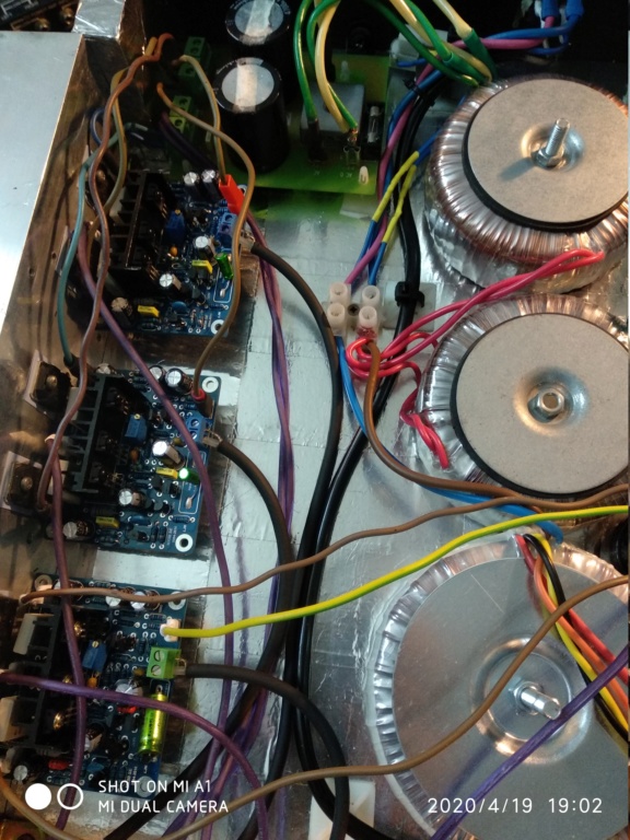
I see you have the old version of mx50x2,it needs a 100uf capacitor after 68ohm resistor at each power trace (+) and (-) on amplifier board.
I see you have the old version of mx50x2,it needs a 100uf capacitor after 68ohm resistor at each power trace (+) and (-) on amplifier board.
This is an old pic - the mods have already been done.
I found the instability when I first built it.
But thanks!
- Home
- Amplifiers
- Solid State
- LJM MX50 kit amp